In modern electronic equipment, resistors are among the most widely used passive components. Unlike fixed resistors, which provide a predetermined resistance value, a Variable Resistor allows the resistance to be adjusted within a specific range. This makes it useful in circuits where voltage, current, gain, signal level, or other electrical parameters need to be adjusted.
When inspecting a PCB Circuit Board, identifying different PCB Components correctly is important for circuit analysis, troubleshooting, maintenance, and repair. A variable resistor can usually be distinguished from a fixed resistor by its adjustable mechanism, terminal configuration, size, and PCB mounting position.
This guide explains what a Variable Resistor does, the main types available, and how to identify one on a PCB.
What Is a Variable Resistor?
A Variable Resistor is an electronic component whose resistance value can be manually adjusted. It generally consists of a resistive element and a movable contact, such as a rotating shaft, sliding contact, or adjustable wiper.
As the position of the wiper changes, the effective length of the resistive element changes. This changes the resistance between the terminals and allows the component to regulate current or voltage in an electronic circuit.
Depending on the application, a Variable Resistor can be used for:
- Adjusting circuit voltage
- Controlling current
- Setting signal levels
- Adjusting amplifier gain
- Controlling display brightness
- Adjusting motor speed
- Calibrating electronic equipment
- Controlling audio volume
- Setting operating parameters during production or maintenance
For example, an audio amplifier may use a potentiometer to adjust volume, while a precision electronic device may use a trimmer resistor for calibration.
How Does a Variable Resistor Work?
The operating principle of a Variable Resistor is relatively simple. It contains a resistive track and a movable contact.
When the movable contact changes position, the resistance between the selected terminals changes accordingly. In a three-terminal configuration, the component can function either as a voltage divider or as a variable resistance.
When two terminals are used, the component generally functions as a variable resistor or rheostat. When all three terminals are used, it commonly functions as a potentiometer and provides an adjustable voltage output.
The resistance range is normally specified by the manufacturer. For example, a component marked 10 kΩ may provide a maximum resistance of approximately 10 kΩ between its two fixed terminals.
Main Types of Variable Resistors
Different types of Variable Resistor are available for different applications. The most common types include potentiometers, trimmer resistors, rheostats, and resistance boxes.
1. Potentiometer
A Potentiometer is one of the most common types of adjustable resistor. It normally has three terminals:
- Two fixed terminals connected to the ends of the resistive element
- One wiper terminal connected to the movable contact
The wiper moves along the resistive element when the shaft or slider is adjusted.
Potentiometers are widely used for user-adjustable controls, including:
- Audio volume
- Display brightness
- Analog signal adjustment
- Equipment settings
- Amplifier gain control
Because the user can frequently adjust the resistance, potentiometers are commonly found on control panels and electronic equipment.
2. Trimmer Resistor
A Trimmer Resistor is designed primarily for infrequent adjustment. Unlike a conventional potentiometer, it is normally adjusted during manufacturing, calibration, servicing, or testing rather than during normal operation.
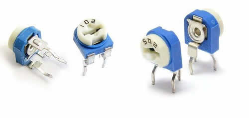
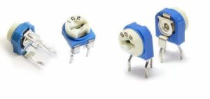
Trimmer resistors are usually compact and often include a small adjustment slot that can be turned with a screwdriver.
On a PCB, they are particularly easy to identify because the component typically has a small adjustment screw or slot on its top surface.
Common applications include:
- Circuit calibration
- Sensor adjustment
- Oscillator frequency adjustment
- Voltage regulation
- Amplifier bias adjustment
- Factory calibration
3. Rheostat
A Rheostat is a variable resistor generally used to control current. It typically uses two terminals and is connected in series with the load.
Changing the position of the movable contact changes the effective resistance in the circuit, which in turn changes the current.
Rheostats are more commonly associated with applications requiring higher current or power handling than small signal potentiometers.
4. Resistance Box
A resistance box provides selectable resistance values rather than continuously adjusting resistance with a conventional wiper.
Different resistance values can be selected through switches or other mechanisms. Resistance boxes are commonly used for laboratory testing, circuit development, measurement, and calibration.
How to Identify a Variable Resistor on a PCB
When examining a PCB Circuit Board, several physical characteristics can help distinguish a Variable Resistor from other Electronic Components.
1. Check the Number of Terminals
A common Variable Resistor has three terminals.
Two terminals are connected to the ends of the resistive element, while the third terminal is connected to the movable wiper.
However, the number of visible terminals alone should not be treated as absolute proof. Some variable resistors may be configured or used with only two terminals.
Therefore, terminal count should be combined with other identification characteristics.
2. Look for an Adjustment Mechanism
One of the easiest ways to identify a Variable Resistor is to look for an adjustment mechanism.
A trimmer resistor may have:
- A screwdriver slot
- A small adjustment screw
- A rotary adjustment mechanism
- A recessed adjustment opening
If a small component on the PCB has a slot that can be adjusted using a screwdriver, it is likely to be a trimmer-type Variable Resistor.
3. Check the Component Marking
Many PCB Components have printed markings indicating their resistance value, part number, or electrical characteristics.
Depending on the manufacturer and package, markings may include resistance values such as:
- 1 kΩ
- 5 kΩ
- 10 kΩ
- 100 kΩ
Some modern surface-mount components may have limited or no visible markings, so the PCB reference designator and circuit documentation may also be necessary.
4. Examine the Physical Size and Shape
Variable resistors come in many different packages.
Small trimmer resistors are commonly compact and may have a square, rectangular, or circular body. Larger wire-wound variable resistors are physically larger because they are designed to dissipate more power.
Compared with ordinary fixed resistors, adjustable components often have a more distinctive body shape because they require additional mechanical structures for adjustment.
5. Identify the Mounting Orientation
Variable resistors can be mounted vertically or horizontally on a PCB.
A vertical trimmer is usually mounted with its terminals extending downward while the adjustment mechanism is accessible from the top or side.
A horizontal configuration may position the terminals at an angle relative to the component body, allowing the component to lie closer to the surface of the PCB Circuit Board.
The mounting style is mainly determined by PCB space, accessibility, component height, and the intended adjustment method.
Common Appearance Characteristics
The following characteristics can help identify a Variable Resistor during PCB inspection:
Three terminals: Many common variable resistors have three electrical terminals.
Adjustment slot: Trimmer-type devices frequently have a screwdriver-accessible adjustment slot.
Distinctive package: The body is often different from that of a conventional fixed resistor.
Resistance marking: The nominal resistance value may be printed or encoded on the component.
Movable contact: The internal wiper mechanism allows the resistance to be changed.
Limited quantity: Many control circuits use only a small number of variable resistors, making them relatively easy to locate during a visual inspection.
However, appearance alone is not always sufficient. For reliable identification, technicians should combine visual inspection with the PCB schematic, component reference designators, datasheets, and electrical measurements.
Variable Resistor vs. Fixed Resistor
The primary difference between a fixed resistor and a Variable Resistor is adjustability.
A fixed resistor has a predetermined resistance value. Once manufactured, its nominal resistance cannot normally be adjusted by the user.
A Variable Resistor, on the other hand, provides an adjustable resistance range.
For example, a 10 kΩ potentiometer can provide different resistance values between the wiper and either end terminal depending on the position of the shaft.
This flexibility makes variable resistors especially useful in circuits requiring calibration or manual adjustment.

Variable Resistors in PCB Design and Manufacturing
From a PCB design perspective, variable resistors require additional consideration because their mechanical adjustment mechanism must remain accessible.
Designers should consider:
- Component orientation
- Adjustment accessibility
- Clearance around the adjustment mechanism
- Component height
- Mechanical interference
- Electrical isolation
- Power dissipation
- Thermal conditions
- Assembly requirements
During PCB manufacturing and assembly, the component footprint must also accurately match the selected part.
For automated SMT assembly, the footprint, pad dimensions, component orientation, and placement data should be verified before production. Incorrect footprint design can lead to assembly problems even when the electrical schematic is correct.
At Kingda, PCB manufacturing considerations can be incorporated into the design review process to help ensure that component selection, PCB layout, and manufacturing requirements are properly aligned.
How to Test a Variable Resistor
Visual inspection is useful, but electrical testing can provide additional confirmation.
A multimeter can be used to measure resistance between the two fixed terminals. This measurement should generally correspond to the component’s nominal maximum resistance.
The resistance between the wiper and either fixed terminal should change as the adjustment mechanism is rotated or moved.
For example, when testing a potentiometer:
- Disconnect power from the circuit.
- Identify the three terminals.
- Measure resistance between the two outer terminals.
- Adjust the shaft or slider.
- Measure resistance between the wiper and one outer terminal.
- Confirm that the resistance changes smoothly.
If the resistance does not change, changes abruptly, or shows an open circuit where it should not, the component may be damaged.
When testing a component while it remains installed on a PCB, other parallel circuit paths can affect the measurement. For accurate results, the component may need to be partially or completely isolated from the circuit.
Common Applications of Variable Resistors
Variable Resistors are widely used in electronic equipment because they provide a simple method for adjusting circuit parameters.
Typical applications include:
- Audio equipment
- Industrial control systems
- Measurement instruments
- Power supplies
- Sensor circuits
- Motor control systems
- Communication equipment
- Consumer electronics
- Test and calibration equipment
In small-signal applications, compact potentiometers and trimmer resistors are particularly common. For higher-power applications, specialized wire-wound variable resistors may be selected to withstand greater current and power dissipation.
Important Considerations When Selecting a Variable Resistor
Choosing the correct Variable Resistor involves more than selecting the desired resistance value.
Important parameters include:
Resistance Range
The maximum resistance should match the requirements of the circuit.
Power Rating
The resistor must be capable of dissipating the expected power without excessive temperature rise.
Adjustment Type
Rotary, slider, and screwdriver-adjusted mechanisms are available for different applications.
Tolerance
Resistance tolerance determines how closely the actual resistance matches the specified nominal value.
Mechanical Size
The component must fit within the available PCB area and meet the equipment’s mechanical requirements.
Adjustment Life
For frequently adjusted applications, the component should have sufficient mechanical endurance.
Environmental Conditions
Temperature, humidity, vibration, contamination, and other environmental factors can affect long-term reliability.
Conclusion
Identifying a Variable Resistor on a PCB Circuit Board is relatively straightforward when several characteristics are considered together. The number of terminals, adjustment mechanism, component shape, resistance markings, mounting orientation, and PCB footprint can all provide useful clues.
The most common types include the Potentiometer, Trimmer Resistor, Rheostat, and resistance box. Although they share the same basic principle of adjustable resistance, their structures and applications differ significantly.
For PCB designers, manufacturers, and maintenance engineers, correctly identifying these PCB Components is important for circuit analysis, troubleshooting, component replacement, and production quality control.
When combined with proper PCB design practices, accurate component selection, DFM review, and controlled manufacturing processes, variable resistors can provide reliable and precise adjustment throughout the service life of electronic equipment.