How to Test a Capacitor on a PCB: PCB Capacitor Testing Methods & Troubleshooting Guide
Capacitors are among the most common passive components found on a PCB (Printed Circuit Board). They play essential roles in power filtering, decoupling, energy storage, timing, signal coupling, noise suppression, and voltage stabilization.
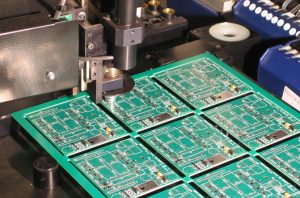
When a capacitor deteriorates or fails, the effects can range from increased power-supply ripple and unstable operation to intermittent resets, excessive heating, distorted signals, or complete circuit failure. However, diagnosing a capacitor on an assembled board is not always straightforward because the capacitor is electrically connected to other components and circuit paths.
So, How to Test a Capacitor on a PCB accurately?
Depending on the capacitor type and the diagnostic objective, engineers and technicians can use visual inspection, a digital multimeter, an ESR meter, an LCR meter, or an oscilloscope. Some tests can be performed directly on the assembled PCB, while others are more reliable after isolating or removing the capacitor from the circuit.
This guide explains practical PCB Capacitor Testing methods, including how to test capacitors without removing them from the PCB, how to interpret measurements, and when component removal is necessary for more accurate diagnosis.
What Is a Capacitor?
A capacitor is a two-terminal passive electronic component consisting of two conductive electrodes separated by a dielectric material.
Its basic electrical behavior allows it to store and release electrical energy. In AC circuits, a capacitor’s impedance depends on frequency, allowing it to perform different functions depending on the circuit design.
Common capacitor applications include:
- Power-supply filtering
- DC voltage smoothing
- Power-rail decoupling
- Signal coupling
- Noise suppression
- Timing circuits
- Energy storage
- Resonant circuits
- RF and high-frequency filtering
A capacitor can also be used to block steady-state DC while allowing AC components to pass, but this behavior depends on how the capacitor is connected within the circuit.
Common capacitor technologies used on PCBs include:
- Aluminum electrolytic capacitors
- Tantalum capacitors
- Ceramic capacitors
- Film capacitors
- Polymer capacitors
- Supercapacitors for specialized applications
Capacitors are available in both through-hole and surface-mount packages.
Signs of a Failed Capacitor on a PCB
PCB Troubleshooting often begins with identifying symptoms rather than immediately replacing components.
A defective capacitor can produce different symptoms depending on its location and function in the circuit.
Common signs include:
1. PCB Fails to Power On
A shorted capacitor on a power rail can create excessive current demand and cause a power supply or protection circuit to shut down.
However, a no-power condition does not automatically indicate a capacitor failure. Other possibilities include damaged ICs, MOSFETs, fuses, connectors, or power-supply components.
2. Random Shutdowns or Restarts
A capacitor with significantly increased ESR or reduced capacitance may provide inadequate filtering or energy storage, causing instability in sensitive circuits.
This can sometimes result in:
- Random resets
- System shutdowns
- Boot failures
- Intermittent operation
3. Excessive Voltage Ripple
A deteriorated filtering capacitor can allow excessive ripple voltage to remain on a DC power rail.
Oscilloscope measurements are particularly useful for identifying this type of problem.
4. Excessive Heating
A capacitor with high leakage current, internal damage, or increased ESR may generate abnormal heat.
However, overheating can also originate from surrounding components, so thermal symptoms should be investigated systematically.
5. Distorted or Unstable Signals
Capacitors used in filtering, coupling, timing, or signal-conditioning circuits can affect waveform shape and frequency response when their electrical characteristics change.
6. Physical Damage
Visible signs can include:
- Bulging aluminum electrolytic capacitor
- Leakage
- Cracked ceramic capacitor
- Burn marks
- Discoloration
- Damaged package
- Lifted or damaged solder joints
A capacitor may also fail electrically without showing any visible damage.
How to Test a Capacitor on a PCB
There is no single test method suitable for every capacitor or every PCB.
The correct method depends on:
- Capacitor type
- Capacitance value
- Rated voltage
- Circuit topology
- Accessibility
- Required measurement accuracy
- Whether the board is powered
- Whether the capacitor is connected in parallel with other components
The following methods provide a practical troubleshooting sequence.
1. Prepare the PCB Before Testing
Safety and preparation are essential before performing PCB Capacitor Testing.
Disconnect the Power
Turn off the equipment and disconnect the PCB from all external power sources.
Do not measure resistance or capacitance on an energized circuit unless the test instrument and procedure are specifically designed for that purpose.
Discharge Stored Energy
Capacitors can retain electrical charge after power has been removed.
Large capacitors, particularly those used in power supplies and high-voltage circuits, may remain charged for a significant period.
Use an appropriate controlled discharge procedure. A properly selected resistor or dedicated discharge tool may be used where appropriate.
Do not routinely short a capacitor directly with a screwdriver because this can create a high-current discharge, damage the component or PCB, and create a safety hazard.
Use ESD Protection
When working with sensitive electronics, use appropriate ESD precautions, including:
- ESD wrist straps where appropriate
- ESD-safe work surfaces
- Proper grounding
- Suitable handling procedures
Before connecting test equipment, verify that the PCB is safe to work on and that potentially hazardous voltages have been discharged.
2. Perform a Visual Inspection
Visual inspection is usually the fastest first step in PCB Troubleshooting.
For aluminum electrolytic capacitors, look for:
- Bulging tops
- Leakage
- Deformed cases
- Vent activation
- Corrosion
- Discoloration
- Burn marks
For ceramic and other SMD capacitors, inspect for:
- Cracks
- Chipped bodies
- Burn marks
- Discoloration
- Damaged solder joints
- Mechanical stress around the component
A cracked MLCC, for example, may develop an electrical short or intermittent failure due to mechanical stress.
However, visual inspection cannot identify every defective capacitor. Many capacitors fail electrically while retaining a normal external appearance.
3. Test a Capacitor with a Digital Multimeter
A digital multimeter is one of the most accessible tools for basic PCB Capacitor Testing.
If the multimeter includes a capacitance function, follow these steps:
- Turn off and disconnect the PCB.
- Confirm that the capacitor has been safely discharged.
- Set the multimeter to capacitance mode.
- Connect the probes to the capacitor terminals.
- Allow the reading to stabilize.
- Compare the measured value with the capacitor’s marked value and specified tolerance.
For polarized capacitors, observe the correct polarity when using instruments that require polarity-sensitive connections.
Can You Test a Capacitor in Resistance Mode?
Resistance mode can provide a basic indication of capacitor behavior, but it should not be treated as a definitive capacitance test.
A capacitor may initially appear as a relatively low resistance and then move toward a higher resistance as it charges from the multimeter’s test voltage.
A continuously very low resistance may suggest a shorted capacitor, while a continuously high resistance may be consistent with an open capacitor or may simply reflect the behavior of the circuit.
The key limitation is that in-circuit measurements can be misleading.
Other components connected to the same net can create parallel current paths. For example, resistors, semiconductor junctions, IC inputs, inductors, and other capacitors can all affect the measured resistance.
Therefore:
A multimeter reading alone does not always prove that a capacitor is defective.
This is especially important when testing a capacitor without removing it from the PCB.
4. Test Capacitors on a PCB with an ESR Meter
An ESR meter measures Equivalent Series Resistance (ESR) and is particularly useful for evaluating many electrolytic capacitors.
A capacitor can have approximately correct capacitance while still exhibiting excessive ESR.
High ESR can cause:
- Increased ripple
- Poor filtering
- Voltage instability
- Excessive heating
- Reduced power-supply performance
This makes ESR testing valuable when troubleshooting aging electrolytic capacitors.
Can an ESR Meter Test a Capacitor In-Circuit?
In many cases, an ESR meter can test capacitors while they remain installed on the PCB, which is one of its major practical advantages.
However, in-circuit ESR measurements are not universally reliable. The surrounding circuit can influence the result, and the instrument’s test method and operating frequency matter.
For this reason, compare the measured value with:
- Manufacturer specifications
- Component datasheets
- Known-good components
- Similar capacitors on the same PCB
- Appropriate ESR reference tables when applicable
An ESR meter can be especially useful when several similar electrolytic capacitors are installed on a power-supply board.
5. Test a PCB Capacitor with an Oscilloscope
An oscilloscope provides a different type of information from a multimeter or LCR meter.
Instead of primarily measuring a component’s nominal value, an oscilloscope allows engineers to observe the actual voltage waveform in the operating circuit.
This is particularly useful for power-supply and signal-integrity troubleshooting.
For example, excessive ripple on a DC power rail may indicate a problem with:
- Filtering capacitors
- Power regulators
- Rectifiers
- Inductors
- Load conditions
- Control circuitry
A typical troubleshooting process is:
- Power the PCB under safe operating conditions.
- Connect the oscilloscope using an appropriate probing method.
- Measure the relevant power rail or signal node.
- Observe ripple, noise, transients, or waveform distortion.
- Compare the measured waveform with the expected operating behavior.
For high-frequency circuits, probe selection and grounding technique are critical. An excessively long oscilloscope ground lead can introduce measurement artifacts and may make a clean waveform appear noisy.
Measuring Capacitor Charging and Discharging
An oscilloscope can also be used to observe a capacitor’s charging and discharging behavior in a controlled test circuit.
For a simple RC network, the time constant is:
τ = R × C
where:
- τ is the RC time constant
- R is resistance
- C is capacitance
The capacitor voltage follows an exponential charging or discharging curve under ideal conditions.
Comparing the measured waveform with the expected RC response can help identify abnormal capacitance, leakage, circuit loading, or other problems.
This technique is particularly useful when evaluating a capacitor as part of a known circuit rather than simply measuring its nominal capacitance.
6. Test a Capacitor with an LCR Meter
An LCR Meter provides more detailed component characterization than a basic multimeter.
It can measure parameters such as:
- Capacitance
- Inductance
- Resistance
- Dissipation factor
- Quality factor
- Equivalent series resistance, depending on the instrument
For accurate component-level testing, the capacitor may need to be removed from the PCB or at least electrically isolated from surrounding circuitry.
The basic process is:
- Disconnect the PCB from power.
- Safely discharge the capacitor.
- Isolate or remove the capacitor when necessary.
- Connect it to the LCR meter.
- Select the appropriate test frequency.
- Measure capacitance and relevant loss parameters.
- Compare the results with the manufacturer’s specifications.
Test frequency matters because capacitor impedance and loss characteristics can vary with frequency.
For high-frequency or precision applications, measuring only capacitance at one frequency may not provide enough information about real-world performance.
In-Circuit vs. Out-of-Circuit Capacitor Testing
One of the most important concepts in How to Test a Capacitor on a PCB is understanding the difference between in-circuit and isolated testing.
| Test Method | Can Be Used In-Circuit? | Main Advantage | Main Limitation |
|---|---|---|---|
| Visual inspection | Yes | Fast and non-invasive | Cannot detect hidden electrical faults |
| Multimeter capacitance | Sometimes | Simple and accessible | Parallel components can affect readings |
| Resistance test | Sometimes | Useful for basic screening | Not a definitive capacitor test |
| ESR meter | Often | Useful for many electrolytic capacitors | Circuit topology can affect results |
| Oscilloscope | Yes | Shows real operating waveform | Requires circuit knowledge |
| LCR meter | Usually better when isolated | Detailed component characterization | May require component removal |
The general rule is simple:
In-circuit testing is convenient for screening; isolated testing is generally more reliable for precise component characterization.
How to Test a Capacitor Without Removing It from a PCB
For maintenance and field troubleshooting, removing components is not always desirable.
A practical non-destructive sequence is:
Step 1: Visual Inspection
Look for physical signs of damage.
Step 2: Power-Off Resistance Check
Check whether the capacitor’s associated power rail or circuit node exhibits an abnormal resistance, while remembering that the reading represents the entire connected network rather than necessarily the capacitor alone.
Step 3: ESR Measurement
For suitable capacitors, use an ESR meter to screen for abnormal ESR without removing the component.
Step 4: Compare with Similar Components
If several capacitors have the same specification and are connected to similar circuit sections, compare their measurements.
Step 5: Observe Operating Waveforms
Use an oscilloscope to check ripple, noise, transient behavior, or signal distortion.
Step 6: Isolate the Component if Necessary
If the results remain ambiguous, lift one terminal or remove the capacitor and perform an isolated capacitance/LCR test.
This approach reduces unnecessary rework while improving diagnostic confidence.
How to Get Accurate PCB Capacitor Test Results
Accurate testing requires more than selecting the right instrument.
Compare Measurements with the Datasheet
Check:
- Rated capacitance
- Capacitance tolerance
- Rated voltage
- ESR
- Leakage current
- Dissipation factor
- Temperature characteristics
Not every capacitor is expected to measure exactly its nominal value.
Consider Temperature
Capacitance, ESR, leakage, and other parameters can change with temperature.
Ceramic capacitors, particularly those using different dielectric classes, can exhibit significant capacitance variation depending on DC bias and temperature.
Therefore, measurements should be interpreted according to the capacitor’s specified operating conditions.
Account for Circuit Loading
A PCB is an interconnected electrical network. Measuring one capacitor in-circuit may also measure the effects of other components.
This is why an apparently abnormal reading does not automatically mean that the capacitor itself has failed.
Use Known-Good Components for Comparison
Comparative testing can be highly effective when troubleshooting several identical circuits or multiple capacitors with the same part number.
Wait for Instrument Stabilization
Some instruments require additional time to stabilize when measuring larger capacitances or components with significant leakage.
Follow the instrument manufacturer’s instructions.
Common Mistakes When Testing Capacitors on a PCB
Avoid the following troubleshooting errors.
Mistake 1: Testing an Energized PCB in Resistance Mode
Resistance and capacitance measurements generally require the circuit to be de-energized.
Mistake 2: Assuming Every Low Resistance Means a Shorted Capacitor
Other components may create a low-resistance path.
Mistake 3: Assuming Every Electrolytic Capacitor with Normal Capacitance Is Good
A capacitor can exhibit acceptable capacitance but excessive ESR or leakage.
Mistake 4: Replacing a Capacitor Without Finding the Root Cause
If a regulator, MOSFET, rectifier, or load caused abnormal electrical stress, simply replacing the capacitor may not solve the underlying problem.
Mistake 5: Ignoring Polarity
Electrolytic and tantalum capacitors may be polarity-sensitive. Incorrect installation can cause serious damage.
Mistake 6: Using an Oscilloscope with Poor Probing Technique
Improper grounding and excessive probe-loop area can introduce false noise or ringing into the measurement.
When Should You Remove a Capacitor from the PCB?
Component removal is appropriate when:
- In-circuit measurements are ambiguous
- The capacitor is connected in parallel with multiple components
- Precise capacitance measurement is required
- Leakage current must be characterized
- LCR measurements are required
- ESR results are inconsistent
- The component shows physical damage
- The circuit is too complex for reliable in-circuit interpretation
In some cases, lifting one terminal can isolate the capacitor sufficiently for testing. However, this should only be done when the PCB design and component construction allow safe rework.
For fine-pitch SMD components, multilayer boards, HDI boards, or high-reliability assemblies, uncontrolled rework can damage pads, traces, vias, or nearby components.
PCB Capacitor Testing and Troubleshooting Workflow
A systematic PCB Repair Process is more reliable than randomly replacing components.
A practical workflow is:
Symptom Identification
↓
Power-Off Safety Check
↓
Visual Inspection
↓
Resistance/Continuity Screening
↓
ESR or Capacitance Test
↓
Oscilloscope Analysis
↓
Component Isolation if Required
↓
LCR/Component-Level Measurement
↓
Component Replacement
↓
Functional Testing
This approach helps reduce unnecessary component replacement and minimizes the risk of damaging the PCB during troubleshooting.
The Role of Capacitors in PCB Design
Capacitor selection begins during PCB Design, long before the board reaches the troubleshooting stage.
Engineers must consider:
- Capacitance value
- Voltage rating
- Tolerance
- Dielectric type
- ESR
- ESL
- Temperature range
- DC-bias characteristics
- Ripple-current capability
- Package size
- Placement requirements
For power decoupling, capacitors are typically placed close to the relevant IC power pins to reduce unwanted inductance in the current path.
For high-speed circuits, capacitor package selection and PCB layout can significantly affect high-frequency performance.
For power electronics, capacitor ripple-current capability, thermal conditions, lifetime, and ESR may be particularly important.
Therefore, reliable capacitor performance depends on both component selection and PCB layout.
How Kingda Can Support PCB Manufacturing and Assembly
Reliable capacitor performance begins with appropriate PCB Manufacturing, component selection, PCB layout, and assembly processes.
For projects requiring new PCB production or replacement boards, Kingda can support application-specific PCB manufacturing requirements and help customers develop boards according to their electrical, mechanical, and production specifications.
For existing designs, important documentation may include:
- PCB fabrication data
- PCB layout files
- Bill of Materials (BOM)
- Assembly drawings
- Component specifications
- Testing requirements
- Electrical specifications
Providing complete and accurate documentation helps ensure that capacitor footprints, polarity markings, component clearances, copper structures, and assembly requirements are correctly implemented.
For troubleshooting or replacement projects, identifying the failed capacitor is only one part of the process. The underlying electrical cause should also be evaluated to prevent repeated failures in the replacement board.
Conclusion
Learning How to Test a Capacitor on a PCB is an important skill for PCB troubleshooting, maintenance, repair, and electronics engineering.
A practical diagnostic process begins with visual inspection and safe power-off testing. A multimeter can provide basic capacitance or resistance information, while an ESR meter is particularly useful for screening many electrolytic capacitors. An oscilloscope can reveal ripple, noise, and abnormal waveforms during actual circuit operation, while an LCR meter provides more detailed component-level characterization.
However, no single measurement should automatically be interpreted as proof of capacitor failure. In-circuit testing is affected by the surrounding circuit, parallel components, measurement frequency, temperature, and instrument characteristics. When accurate component-level verification is required, isolating or removing the capacitor may be necessary.
Ultimately, effective PCB Troubleshooting combines measurement data, circuit knowledge, component specifications, and systematic fault isolation. By using the appropriate testing method and avoiding unnecessary rework, engineers and technicians can identify capacitor-related problems more efficiently while reducing the risk of further PCB damage.