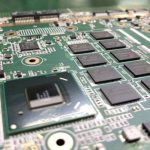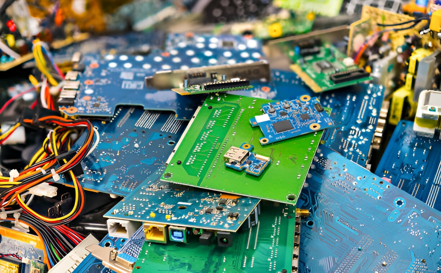
An Industrial PCB is a printed circuit board designed for industrial electronic equipment and systems rather than conventional consumer electronics. Industrial environments often involve demanding operating conditions, including high or low temperatures, humidity, dust, vibration, mechanical stress, chemical exposure, electrical noise, and continuous operation.
Compared with standard consumer-grade circuit boards, an Industrial Circuit Board must provide higher reliability, durability, and long-term electrical performance. Depending on the application, it may also require specialized materials, reinforced mechanical structures, controlled impedance, enhanced thermal performance, and additional environmental protection.
Industrial PCBs are essential components in complex machinery and automated systems. They are widely used in industrial automation, automotive equipment, telecommunications, energy systems, factory control equipment, robotics, CNC machines, and other applications where PCB failure can cause equipment downtime, production losses, or safety risks.
For this reason, industrial PCB design and manufacturing must consider not only electrical performance but also thermal, mechanical, environmental, and regulatory requirements.

Common Materials Used in Industrial PCBs
Different industrial applications require different PCB materials. Material selection should be based on operating temperature, mechanical requirements, electrical characteristics, thermal performance, cost, and expected service life.
FR-4
FR-4 is one of the most widely used PCB substrate materials. It consists of glass-fiber reinforcement combined with epoxy resin and provides a good balance of electrical insulation, mechanical strength, thermal performance, and cost.
For industrial applications, different grades of FR-4 can be selected according to performance requirements, including high-Tg, high-speed, and halogen-free materials. High-Tg materials are particularly useful when the PCB must withstand elevated operating or processing temperatures.
Polyimide
Polyimide is commonly used for flexible PCBs and applications requiring excellent flexibility and thermal stability. It maintains reliable electrical performance under repeated bending and demanding temperature conditions.
Polyimide-based flexible circuits are widely used where space is limited or where the circuit must conform to moving or irregular mechanical structures.
Metal-Core Materials
Metal-core PCBs are suitable for applications requiring efficient heat dissipation. Aluminum is commonly used as the metal core because of its relatively high thermal conductivity, mechanical strength, and cost efficiency.
Metal-core construction can help transfer heat away from power components and reduce thermal stress in high-power industrial electronics.
High-Performance and Specialized Materials
High-frequency, high-speed, high-voltage, or high-temperature industrial applications may require specialized laminates. Material selection should take into account dielectric constant, dissipation factor, thermal expansion, glass transition temperature, moisture resistance, and electrical insulation requirements.
Industrial PCB Manufacturing Process
Industrial PCB Manufacturing requires strict process control because the finished board may be expected to operate continuously under demanding conditions. Although the exact process varies according to PCB structure and technology, a typical manufacturing workflow includes the following stages.
1. PCB Design and Prototyping
The PCB Design process begins with electrical and mechanical requirements. Engineers define the circuit architecture, component placement, routing, layer stackup, power distribution, grounding, thermal paths, and mechanical dimensions.
Design-for-manufacturing (DFM) checks should be performed before production to identify potential issues involving trace width, spacing, drill sizes, copper thickness, annular rings, component clearances, and fabrication tolerances.
Prototype boards are often produced during the research and development stage so that electrical, thermal, mechanical, and functional performance can be verified before volume production.
2. PCB Layout Transfer
After the design is finalized, the circuit pattern is transferred to the PCB material through imaging and photolithographic processes. A photosensitive material is applied to the copper surface and selectively exposed to ultraviolet light according to the required circuit pattern.
This process determines the accuracy of the conductive features and therefore requires precise process control.
3. Copper Etching
During etching, unwanted copper is removed from the board while the required conductive patterns remain. Proper control of etching parameters is important for maintaining the designed trace width and spacing.
For fine-line industrial PCBs, manufacturing tolerances must be carefully controlled to ensure consistency between the PCB design and the finished board.
4. Drilling
Mechanical drilling or laser drilling is used to create through-holes, vias, and other required openings.
The drilling process must maintain accurate hole diameter, position, depth, and registration. Multilayer and HDI industrial PCBs may require more advanced drilling technologies to form microvias and other interconnection structures.
5. Copper Plating
Copper plating creates conductive connections between PCB layers and builds up copper thickness on drilled holes and exposed surfaces.
Reliable plating is particularly important for industrial applications because poor hole-wall quality or insufficient copper thickness can reduce current-carrying capability and long-term reliability.
6. Solder Mask Application
A solder mask is applied to protect copper circuits from oxidation, contamination, and accidental solder bridging during assembly.
The solder mask also helps define solderable areas around component pads and contributes to the overall durability of the finished PCB.
7. Surface Finish
Depending on the application, industrial PCBs may use surface finishes such as HASL, ENIG, immersion tin, or other suitable technologies.
The selected surface finish should be compatible with the assembly process, environmental conditions, contact requirements, and expected service life.
8. Inspection and Testing
Quality control is a critical part of PCB Manufacturing. Industrial boards may undergo several inspection and testing procedures, including automated optical inspection (AOI), electrical testing, X-ray inspection, dimensional inspection, and visual inspection.
The specific testing plan should be determined according to PCB complexity, application risk, customer requirements, and applicable standards.
Applications of Industrial PCBs
Industrial Industrial PCB technology is used across many industries because modern machines and control systems depend on reliable electronic control and communication.
Industrial Automation
Industrial automation systems rely heavily on PCBs to control motors, sensors, actuators, drives, machine interfaces, and communication networks.
CNC machines, robotic systems, automated production lines, and factory equipment all use circuit boards to coordinate high-speed and high-precision operations.
Industrial automation is also increasingly integrating sensors, machine vision, motion control, and industrial networking. As a result, PCB designs must often support higher processing speeds, more interfaces, and greater component density.
Robotics
Robotic equipment requires PCBs for motor control, sensor processing, communication, power management, and system coordination.
Robotics applications can expose circuit boards to continuous vibration, rapid movement, temperature variations, and electrical noise. Therefore, mechanical stability, connector reliability, thermal control, and Signal Integrity are important considerations.
Automotive Industry
Industrial-grade PCB technology is also used in automotive electronic systems. Applications may include engine control units (ECUs), advanced driver assistance systems, infotainment systems, navigation equipment, communication modules, braking systems, and vehicle power management.
Because automotive electronics can experience vibration, temperature fluctuations, humidity, and electrical transients, the PCB must be designed for reliable operation under demanding environmental conditions.
Industrial Control Systems
Industrial control equipment such as programmable logic controllers (PLCs), human-machine interfaces (HMIs), and distributed control systems (DCS) relies on PCBs to process signals and control industrial operations.
These systems may operate continuously for long periods, making reliability, electrical stability, thermal performance, and resistance to environmental stress especially important.
Telecommunications Equipment
Industrial PCBs are widely used in telecommunications equipment, including switching systems, routers, network equipment, wireless communication systems, and base-station electronics.
These applications often require high-speed signal transmission and controlled impedance. Careful stackup design, grounding, shielding, and Signal Integrity management can help reduce signal loss, crosstalk, and electromagnetic interference.
Energy and Power Systems
Industrial PCBs are used in power generation, power conversion, energy storage, and renewable energy systems.
Applications can include generator control systems, power converters, battery management systems, solar power equipment, wind power systems, and smart-grid infrastructure.
Power electronics often generate significant heat and electrical noise, so Thermal Management, power distribution, insulation, and EMC design are essential.
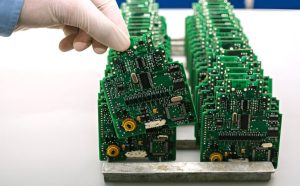
Key Industrial PCB Design Considerations
Designing an industrial board requires a comprehensive approach. Electrical performance alone is not enough; the PCB must also survive the mechanical and environmental conditions expected during operation.
Thermal Management
Thermal Management is one of the most important aspects of industrial PCB design.
- Heat-generating components should be positioned to prevent excessive heat concentration.
- Thermal vias can transfer heat from component pads or copper areas into internal or bottom layers.
- Heat sinks and other thermal structures may be used for high-power components.
- Copper thickness and copper area should be selected according to current and thermal requirements.
- Metal-core construction can be considered when conventional FR-4 cannot provide sufficient thermal performance.
- The enclosure and airflow should also be considered because PCB-level thermal performance depends on the complete system.
Effective Thermal Management helps reduce component temperature, thermal stress, and long-term reliability risks.
Signal Integrity
High-speed industrial systems require careful Signal Integrity management.
Important considerations include:
- Controlled trace impedance
- Appropriate trace width and spacing
- Short and direct high-speed routing
- Proper return-current paths
- Minimized crosstalk
- Controlled via transitions
- Continuous reference planes
- Appropriate termination techniques
A well-designed ground plane can provide a stable return path and help reduce noise and EMI. For high-speed interfaces, the complete stackup should be evaluated before routing begins.
Power Distribution
Industrial equipment may contain high-current loads, motors, relays, power converters, and other demanding circuits.
The PCB should therefore be designed with appropriate power and ground structures. Power traces and copper areas must be sized according to expected current, temperature rise, and allowable voltage drop.
Decoupling capacitors should be placed close to IC power pins to reduce local power-supply noise. High-current paths should also be kept short and designed to minimize unnecessary resistance and inductance.
For high-power applications, designers should consider copper thickness, via capacity, thermal relief structures, connector ratings, and creepage and clearance requirements.
Environmental Protection
Industrial PCBs may be exposed to moisture, dust, chemicals, temperature changes, and other environmental stresses.
Depending on the application, protective measures may include conformal coatings, sealed enclosures, suitable surface finishes, moisture-resistant materials, and appropriate component selection.
Conformal coating can provide additional protection against humidity and contamination, but the coating material and application process should be selected according to the actual operating environment.
Electromagnetic Interference
Industrial environments can contain significant electrical noise generated by motors, switching power supplies, inverters, relays, and other equipment.
PCB designers can reduce EMI risks through:
- Proper grounding strategies
- Controlled return-current paths
- Ground planes
- Filtering components
- Ferrite beads
- Shielding structures
- Appropriate component placement
- Separation of noisy and sensitive circuits
EMI control should be considered from the beginning of the PCB Design process rather than treated as a final-stage correction.
Mechanical Design
Industrial equipment can generate continuous vibration and mechanical shock. PCB thickness, mounting-hole locations, component height, connector placement, and board support should therefore be considered during the mechanical design stage.
Heavy components should be properly supported when necessary, and mounting structures should minimize mechanical stress transferred to solder joints and PCB materials.
For equipment operating under severe vibration, designers should also consider PCB bending, connector retention, solder-joint fatigue, and enclosure integration.
Standards and Compliance
Industrial PCBs may need to comply with various technical and regulatory requirements depending on their application and market.
Common considerations include IPC requirements for PCB fabrication and acceptability, UL-related safety requirements, electromagnetic compatibility (EMC), and RoHS requirements for restricted substances.
The applicable standards should be determined according to the end product, operating environment, destination market, and customer specifications.
Electrical safety is particularly important for industrial equipment operating at high voltage or high power. Appropriate insulation, creepage, clearance, and protective structures should be incorporated into the design.
Reliability Testing for Industrial PCBs
Because industrial equipment may operate continuously for years, reliability testing can be more demanding than for ordinary consumer electronics.
Depending on the application, testing may include:
- Electrical continuity and isolation testing
- AOI inspection
- X-ray inspection
- Thermal cycling
- Temperature and humidity testing
- Vibration testing
- Mechanical stress testing
- Insulation and dielectric testing
- Functional testing
- Burn-in or endurance testing
The exact test requirements should be established according to the product’s risk level and operating conditions.
Challenges in Industrial PCB Manufacturing
Industrial PCB production presents several challenges.
| Challenge | Key Consideration |
|---|---|
| High operating temperature | Select appropriate materials and improve thermal design |
| High current | Increase copper capacity and optimize power distribution |
| Vibration and shock | Strengthen mechanical support and mounting structures |
| Moisture and contamination | Consider conformal coating and environmental protection |
| High-speed signals | Control impedance and improve Signal Integrity |
| EMI | Optimize grounding, routing, filtering, and shielding |
| Long service life | Use reliable materials, components, and manufacturing processes |
| Complex structures | Apply strict DFM and process control |
A successful industrial PCB must balance electrical performance, mechanical durability, thermal behavior, manufacturability, and cost.
Why Choose Kingda for Industrial PCB Manufacturing?
Industrial applications require a manufacturing partner capable of maintaining consistent process control and quality throughout production.
Kingda provides PCB manufacturing and assembly solutions for industrial electronics, supporting different board structures and application requirements. When selecting an industrial PCB supplier, customers should evaluate manufacturing capabilities, material options, quality-control procedures, engineering support, testing capabilities, and communication efficiency.
A reliable supplier should also be able to review PCB fabrication data before production and identify potential manufacturing risks early. This can help reduce design revisions, production delays, and quality problems.
For complex industrial projects, close cooperation between the PCB designer, manufacturer, and assembly provider is particularly important. Early DFM review and engineering communication can improve manufacturability while maintaining the required electrical and mechanical performance.
Conclusion
An Industrial PCB is a critical component of modern industrial equipment. Compared with conventional consumer electronics, industrial applications often place greater demands on reliability, thermal performance, mechanical strength, environmental resistance, and long-term stability.
From industrial automation and robotics to automotive electronics, telecommunications, control systems, and energy equipment, industrial circuit boards support a wide range of critical functions.
Successful industrial PCB development requires careful material selection, robust PCB Design, controlled PCB Manufacturing, effective Thermal Management, reliable power distribution, strong Signal Integrity, EMI control, and appropriate testing.
By considering these factors from the earliest design stage and working with an experienced manufacturing partner such as Kingda, companies can build industrial circuit boards that provide stable performance and dependable operation in demanding environments.