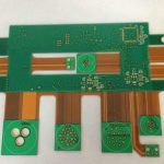
Layout Design Steps for a Controller Board
Layout design can be described in three steps and then takes years to master. The steps are the schematic, the netlist that carries the connectivity across, and the physical layout itself. Everything else, including the placement rules and the routing constraints, is detail that sits inside the third step.
This article follows that sequence for a controller board, where a microcontroller shares the board with a power supply, some analogue inputs and a handful of connectors, and describes the layout decisions that determine whether the finished product is quiet or temperamental.
Schematic, Netlist, Layout: the Three Steps
The schematic captures the circuit and the intent. The netlist is the machine-readable statement of what connects to what, and it is the only thing the layout tool reads. The layout turns that connectivity into copper, and it is where the electrical design meets the mechanical and thermal reality of the product.
A mistake at the schematic stage propagates into both of the later steps, and a mistake at the netlist stage hides itself until test. That is why the sequence should be respected rather than short-circuited: laying out copper before the schematic is settled produces a board that works and cannot be revised.

Setting Up the Schematic for Layout
Two settings in the schematic have a disproportionate effect on the layout. The first is the drawing size and grid, which should match the scale of the circuit so that the sheet is readable and the connectivity is unambiguous. The second is the pin numbering and footprint assignment of every component, which must match the physical part exactly.
It is worth making the schematic easy to check rather than merely tidy. Grouping components by function, keeping decoupling capacitors next to the device they serve in the drawing as well as on the board, and using readable net names all reduce the chance that a mistake survives to the layout. A schematic that cannot be reviewed quickly will not be reviewed at all.
Placement for a Controller Board
Placement starts with the parts that cannot move: connectors, switches, indicators, mounting holes and anything with a defined position in the enclosure. Once those are fixed and locked, the components that carry the most current or generate the most heat are placed, followed by the devices they interact with, and finally the small parts.
Related components belong together. A crystal and its load capacitors belong next to the clock pins they serve, and a reset circuit belongs next to the reset pin. Devices that generate noise, such as switching regulators and clock generators, should be kept away from the microcontroller logic, the memory and any analogue input, and where possible the noisy group should occupy its own region of the board.
Decoupling Capacitor Placement
Every supply pin needs local decoupling, and the value that does most of the work is small. A ceramic capacitor of about 0.1 microfarads placed immediately at the pin provides the high-frequency path, and a bulk electrolytic of around 100 microfarads at the input of the board supply handles the slower load changes.
The placement rule matters more than the value. The capacitor should be on the same side as the device where possible, connected by the shortest possible path to the supply pin and to a ground via immediately beside it. Lead length is inductance, and a high-frequency bypass capacitor with long leads behaves as though it were not there, which is why the layout of the regulator and its local loop is part of the same decision.
Ground Strategy and Grounding Points
A controller board usually has more than one kind of ground: the logic ground, the analogue ground, the chassis or shield, and the return of any power stage. They should be routed separately and joined at one defined place, so that the currents do not share a conductor and turn one circuit into a noise source for another.
A ground plane beneath the signal layers is what gives every return current a short path, and the topology of the connections to it decides how well it works.
The joining strategy depends on frequency. Below a few megahertz, a single-point connection avoids a large circulating loop and is the usual choice. Above roughly ten megahertz, the impedance of the ground conductor itself becomes significant, and a multiple-point connection that gives every return a short local path is better. Whichever is used, the ground conductors should be wide: several millimetres for the main ground and a wider connection at analogue input and output points, where the shared impedance is most damaging.
Track Width and Power Distribution
Track width follows current and process. A useful starting point is that signal traces on a controller board should be no narrower than about 0.3 millimetres, with 0.45 to 0.5 millimetres being a comfortable target where space allows, because the wider trace has lower impedance and is less sensitive to coupling.
Power and ground traces should be wider still, sized from the current rather than from habit, and routed in the same general direction as the signals they serve so that the current paths stay predictable. Filling the unused area of the board with ground copper, connected to the ground net, reduces the impedance of the return path and adds a small amount of shielding. The choice between a solid fill and a grid is covered in the notes on copper flooding, mesh or solid, and it matters mainly for how the board behaves during assembly.
Vias: Capacitance and Mechanical Strength
Every via adds a small capacitance to the net it carries and to any plane it passes through, which is why via capacitance is on the order of ten picofarads for a typical through hole. On a slow digital net that is irrelevant. On a fast clock or a high-impedance analogue node, several vias in series can change the behaviour of the circuit noticeably.

Vias also reduce the mechanical strength of the board locally, because the laminate around the barrel is displaced. Keeping the number of vias low, particularly on high-frequency nets, and avoiding clusters of vias in a small area are both good practice. Where a via is unavoidable, keeping the stub short by choosing a suitable layer transition is more useful than reducing the diameter.
Checking the Layout Before Release
The final check is a pass over the four things that cause most re-spins: footprints against the physical parts, the position and orientation of every connector, the clearance to the mechanical envelope, and the routing of the nets that carry the highest current or the fastest edges.
The characteristics that define PCB quality are a useful checklist to run alongside the rules.
Running a design rule check at the end is necessary but not sufficient, because the rules describe the process rather than the intent. The list of rules is a document to be reviewed alongside the layout, not a substitute for looking at the board. A short review meeting with the layout, the hardware design and whoever will build the board catches more than any automated check.
FAQ
How wide should a signal trace be on a controller board? At least 0.3 millimetres, with 0.45 to 0.5 millimetres as a sensible target. Narrower traces are manufacturable but have higher impedance and couple more readily to their neighbours.
Should the analogue and digital grounds be separate planes? Not necessarily as separate planes, but the currents should occupy separate regions and meet at one defined point. Whether that point is a bridge, a single connection or an area under the converter depends on the frequencies involved.
How many vias are too many? There is no fixed number, but each one adds capacitance and a mechanical discontinuity. Question every via on a clock or high-impedance analogue net, and keep the count low in the region of a sensitive device.