
Copper Flooding: Mesh or Solid, and How to Handle Ground Islands
Filling the empty area of a board with copper is one of the oldest habits in layout, and like most habits it is sometimes applied without much thought. A pour is not decoration and it is not a free improvement. It changes the impedance of nearby traces, it adds capacitance where none was intended, it can create resonant structures, and on a badly planned board it can make an EMI problem worse rather than better. Used with intent, though, a copper flood is one of the most economical tools available: it lowers ground impedance, reduces loop area and improves power distribution at no extra cost.
What Flooding Actually Buys You
The first benefit is impedance. A flood connected to ground gives every return current a wide, low-inductance path back to its source, which reduces the voltage that develops across the ground network when a fast edge switches. The second benefit is loop area. Every signal that has a return path directly beneath it encloses almost no area, and a small loop radiates and receives very little. The third is power distribution: flooded copper near a supply rail reduces the IR drop between the regulator and the load, which raises efficiency and reduces local heating.
None of those benefits require the flood to be electrically clever. They require it to be continuous, well stitched to the reference plane, and free of unnecessary interruptions, which is the same discipline that governs escape routing and pad fanout.
Flooding When the Board Has Several Grounds
Boards with digital, analog, crystal and system grounds cannot simply receive one undifferentiated pour. The usual approach is to divide the surface into regions and flood each region using the ground that dominates it. Digital and analog areas are flooded separately, and the corresponding supply traces are widened before the flood is applied, so that the pour does not have to carry current that a proper trace should carry.
The result is a set of polygons with different shapes, which is expected. What matters is how those polygons are joined. The connection between separate ground regions should be a deliberate, single point, made in a location chosen for the return currents that actually flow there, rather than wherever the last polygon happened to end.
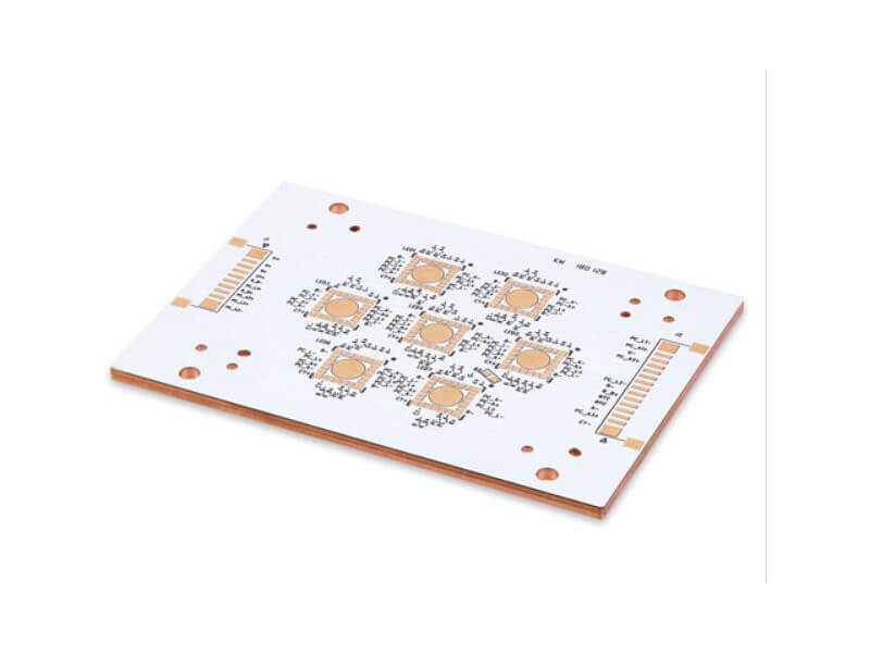
Ground Islands and How to Tie Them Down
A flood inevitably produces islands: regions of copper that are isolated because traces, pads or vias have cut them off from the rest of the net. An island that is connected to nothing is worse than no copper at all, because it is a floating conductor that couples to whatever is nearby and reradiates it. An island that is connected by one narrow neck is only slightly better, since the neck has high inductance and behaves like a stub.
The cure is straightforward. Identify the islands, and place a via in each one that ties it to the ground plane on another layer. A single via is usually enough to convert a floating patch into a useful part of the ground network, and the cost is one drill hit in an area that is otherwise empty. Where the island is large and carries significant high-frequency current, use several vias spaced along it.
The same reasoning applies to the copper that surrounds a via. A pour that generously surrounds every via reduces the inductance of the via connection and improves current sharing; a pour that barely touches each via creates a chain of narrow necks in series.
Crystal Shielding and Local Flooding
A crystal oscillator is a high-frequency source sitting in the middle of the board, and the region around it deserves local treatment. The standard technique is to flood a ring of ground copper around the crystal and its load capacitors, keeping the flood close but not running signal traces beneath the component, and then grounding the metal can of the crystal separately to a nearby ground point with a short, wide connection.
This crystal shielding is not a matter of pouring copper everywhere near the device. The flood should be a defined ring, tied to ground with multiple vias so that the ring itself has a low impedance. Traces that must run near the oscillator should cross the flood on an inner layer beneath a ground plane rather than sharing the surface with it, and the loop formed by the crystal, its capacitors and the ground return should be kept as small as the placement allows.
<img src=”https://www.gopcba.com/wp-content/uploads/2024/09/Inner-layer-UV-expose-and-etching4-1.png” alt=”ground island tied down with stitching vias” />
Mesh Copper Versus Solid Copper
The choice between a mesh pour and a solid pour is not a question of which is better in general. A solid pour is a continuous sheet, which makes it an excellent conductor for low frequencies and provides the lowest impedance return path for DC and low-frequency current. It also has significant thermal mass, which is a problem during wave soldering: a large unbroken copper area can cause the board to warp or to blister as the copper and the laminate expand at different rates.
Mesh copper, drawn as a fine lattice rather than a sheet, has better thermal behaviour and reduces the warping risk. It is also less prone to creating large resonant regions, and for high-frequency circuits where interference rejection is the priority, the mesh form is often preferred. The trade-off is that a mesh has higher inductance than a solid sheet, so it is a poor choice where the pour has to carry substantial current.
The practical rule follows from that: use solid copper where the circuit needs low impedance or carries significant low-frequency current, and use mesh copper where thermal management and high-frequency behaviour dominate. On mixed boards, different regions may reasonably use different forms.
Flooding on Mixed Analog and Digital Boards
Digital boards, and particularly boards built around a microcontroller running in the megahertz range and above, benefit from flooding mainly because it lowers the impedance of the ground plane as a whole. Segregating the flood by functional block and then joining the blocks with dedicated traces is a reasonable technique, since it limits the interaction between one stage of the circuit and the next.
Analog sections need more care. Analog ground is usually required to be a single point ground, and the reason is that a continuous analog plane can carry a return current from a high-level output stage into the reference of a sensitive input stage, producing exactly the interference the design was trying to avoid. Whether the analog ground can be flooded as one sheet therefore depends on the circuit, and it must be decided by tracing the return currents rather than by habit. Where the analog circuit has a single reference point and its blocks do not share return paths, flooding is harmless. Where it does not, the flood should be broken up and each section referenced to its own point.
The same reasoning explains why ground configuration and plane geometry deserve to be reviewed together, and the electrical consequences of splitting a reference are examined in this article on power plane splitting rules.
Reviewing a Flood Before Release
A flood should be checked as a structure, not as a background. Confirm that no island is left floating, that every isolated region has at least one stitching via, that the flood does not short or crowd a pad or via clearance, and that the copper does not form a narrow neck where the return current is expected to flow. Where a flood overlaps a routing layer, verify that it does not create an unintended capacitance on a sensitive node, and where it crosses a boundary between grounds, verify that the crossing is deliberate. The dimensional limits that govern how close that copper may sit to a pad or via are the ones set out in this discussion of via to trace clearance.
FAQ
Should I use a mesh or a solid copper pour? It depends on what the pour is for. Solid copper gives the lowest impedance and is the right choice where the pour carries current or provides a reference. Mesh copper handles heat better, is less prone to warping during wave soldering and suits high-frequency circuits where interference rejection matters more than current capacity.
What should I do with copper islands produced by the pour? Tie each island to the ground plane with at least one stitching via. A floating island is a parasitic conductor that couples to nearby signals and reradiates them, which is worse than having no copper there at all. Large islands may need several vias spaced along their length.
Can the analog ground be flooded as one piece? Only if the analog blocks do not share return paths and the circuit has a genuine single reference point. If a high-level output stage returns through the same copper that serves a sensitive input reference, the flood will couple the interference directly into the measurement, and the ground should be divided and referenced separately.