



Magnetic Coil PCB vs Inductor PCB: Key Differences and How to Choose in 2026
Why Coil and Inductor PCBs Matter
Modern electronics pack more and more electromagnetic function onto the board. Wireless charging, power conversion, NFC and signal filtering all rely on coils and inductors built directly into the PCB. Two terms come up often: magnetic coil PCB and inductor PCB. They are related but serve different purposes. This guide explains how each works, how they differ in structure and performance, and how to pick the right one for your project in 2026.
What Is a Magnetic Coil PCB?
A magnetic coil PCB uses a spiral or ring shaped copper trace on the board to create a magnetic field when current flows. The coil is a planar structure and can be built on a single layer, two layers or a multilayer stack. The design goal is to maximize field strength and coupling efficiency rather than a precise inductance value.
When current passes through the coil, electromagnetic induction produces a magnetic field around the board, which allows energy transfer or signal sensing. Common materials include FR4 for general use, polyimide for flexible coils, and low loss high frequency materials for RF work. Typical applications are Qi wireless charging coils, NFC antennas and inductive sensors.
What Is an Inductor PCB?
An inductor PCB is a design that realizes inductor function on the board. It can be an embedded inductor inside the laminate, a planar inductor built into the layout, or a surface mount SMD inductor soldered onto the board. The key parameters are inductance value, quality factor and DC resistance.
Inductor PCBs are used for energy storage and filtering. They appear in DC DC converters, filter circuits and RF matching networks, where a stable, predictable inductance is important. Compared with a coil PCB, an inductor PCB is more compact and emphasizes precise control of the inductance value and parasitic effects.
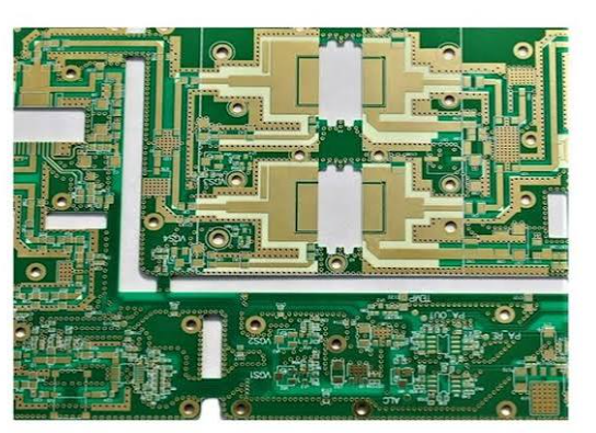
Key Differences Between Coil PCB and Inductor PCB
Function. A magnetic coil PCB focuses on generating a magnetic field and transferring energy, while an inductor PCB focuses on storing energy and filtering signals. Structure. The coil PCB uses a larger spiral or ring coil, while the inductor PCB uses a more compact structure with a precise inductance target. Electrical performance. The coil PCB is designed for coupling efficiency and field strength, while the inductor PCB is designed for a controlled inductance and low loss across frequency. Materials and process. Coil PCBs often use thick copper of 2 to 6 oz to carry current, while inductor PCBs rely on multilayer structure and fine manufacturing. Applications. Coil PCBs fit wireless charging and sensing, while inductor PCBs fit power management and filtering.
Advantages of a Magnetic Coil PCB
A coil PCB is ideal for wireless charging designs because it supports a large area coil and a thin, integrated form factor. It allows very slim products and can be extended to a flexible board so the coil bends with the product. The planar structure keeps the coil consistent and repeatable, which improves charging performance and simplifies assembly.
Advantages of an Inductor PCB
An inductor PCB gives a stable, predictable electrical performance in power systems. It suits high frequency inductor design and reduces the number of discrete components on the board, saving space and improving reliability. Because the inductance is controlled, the filter and converter behave consistently from board to board.
The coil geometry drives the coupling. Trace width, spacing, turns and layer position together set the field shape and the resulting performance. For a charging coil, a larger winding area and thicker copper improve current handling, while a tight tolerance keeps the inductance consistent. For an RF coil, keep the trace impedance stable and the return path short to avoid loss.
Design Considerations
For a magnetic coil PCB, optimize the trace width and spacing to increase current capacity, add shielding layers to reduce electromagnetic interference, use simulation tools to improve the field distribution, and reinforce the thermal design. For an inductor PCB, calculate the inductance precisely, minimize parasitic capacitance and resistance, raise the quality factor for high frequency performance, and use a multilayer stack to keep the size small.
Both designs need close collaboration with the manufacturer. Copper weight, dielectric thickness and tolerance all affect the final performance, so a design review before production makes a big difference.

2026 Price Comparison
As a reference, a magnetic coil PCB prototype run of 1 to 10 boards typically costs about 15 to 80 US dollars per board, a small batch of 100 boards drops to 5 to 20 US dollars per board, and a large run can reach 1 to 5 US dollars per board. Planar inductors generally cost about 2 to 10 US dollars each, while an embedded inductor board runs about 10 to 50 US dollars per board. The main cost drivers are copper thickness and layer count, board size and complexity, process precision and material type.
The inductance tolerance affects the resonant frequency and the filter performance, so a tighter specification is worth paying for when the circuit is sensitive. In a DC DC converter the ripple and efficiency depend on the quality factor, while in a charging pad the coupling coefficient is the dominant figure. Define the target metric before you ask for a quote.
How to Choose
Choose a magnetic coil PCB when you need wireless charging or electromagnetic coupling, when the application relies on generating a magnetic field, or when you need a large or flexible coil. Choose an inductor PCB when you are working on power management, signal filtering or a small, high precision inductance design. The two are not interchangeable in most cases, so match the board to the electrical requirement.
Common Problems and Solutions
Electromagnetic interference. Add a ground plane and shielding structure to contain the field. Thermal management. Use thick copper and thermal vias to move heat away from the coil. Manufacturing tolerance. Work with an experienced supplier who controls trace and layer tolerance tightly. Verification. Use an impedance analyzer and simulation software to validate the inductance and coupling before volume production.
Future Trends
High frequency and miniaturization continue to drive the market. Wireless power transfer PCBs are advancing rapidly, and they are being used more in new energy vehicles, IoT devices and wearables. Low loss substrate materials are becoming common, which helps both coils and inductors perform better at higher frequencies. Expect these components to keep shrinking while gaining capability.
FAQ
What is the biggest difference between a magnetic coil PCB and an inductor PCB? The coil PCB generates a magnetic field, while the inductor PCB stores energy and filters signals.
Can a magnetic coil PCB replace an inductor? In some cases yes, but it is usually not suitable for a high precision inductance requirement.
Which is better for wireless charging? A magnetic coil PCB is the best choice.
Will PCB inductors replace traditional inductors? They are gradually replacing them in high frequency and miniaturized applications.
How do I calculate a PCB inductor? Use a formula or an electromagnetic simulation tool to model the trace geometry.
Get the right build. Match your design to a reliable PCB manufacturing partner, apply PCB design and manufacturing best practices, and follow high frequency PCB design guidance to keep the coil and inductor performance on target.
