Marine Black Box PCB: Design and Manufacturing for Reliable Voyage Data Recording
In commercial shipping and inland waterway transportation, the vessel’s black box is a critical electronic system for recording voyage information and supporting accident investigation. Officially known as a Voyage Data Recorder (VDR) in many marine applications, the system continuously collects and stores important information such as vessel position, speed, heading, engine parameters, communication data, and other operational records.
At the heart of this system is the Marine Black Box PCB, which provides the electrical infrastructure for data acquisition, signal processing, communication, storage, and system control.
Unlike standard electronic circuit boards, marine electronics must operate reliably in environments characterized by high humidity, salt spray, temperature fluctuations, mechanical vibration, shock, and electromagnetic interference. These conditions place significantly higher demands on PCB materials, construction, surface treatment, signal integrity, power management, and assembly quality.
A properly engineered Marine PCB helps maintain stable operation throughout the vessel’s service life while ensuring that critical voyage data remains accurately captured and available when required.
What Is a Marine Black Box PCB?
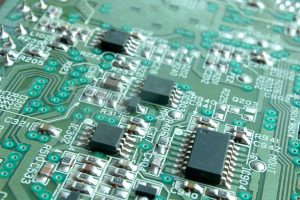
A Marine Black Box PCB is a specialized printed circuit board designed for vessel voyage data recording and monitoring equipment.
It connects sensors, communication interfaces, processing units, memory devices, power circuits, and external monitoring equipment into an integrated electronic system.
Depending on the VDR architecture, the PCB may support the acquisition and processing of:
- GPS position data
- Vessel speed and heading
- Engine operating parameters
- Fuel consumption information
- Water temperature and oil pressure
- VHF communication data
- Radar-related information
- Alarm and navigation signals
- Time and event information
The board must process different types of signals while maintaining stable communication between acquisition modules, processors, memory devices, and external interfaces.
Because recorded information may later be used for operational analysis or accident investigation, data integrity is one of the most important design objectives.
Why Marine Black Box PCBs Require High Reliability
Marine electronics face environmental conditions that are substantially more demanding than those found in many indoor commercial applications.
A vessel may experience:
- High humidity
- Salt spray and corrosive atmosphere
- Wide temperature variations
- Continuous vibration
- Mechanical shock
- Electromagnetic interference
- Long operating cycles
- Limited maintenance opportunities
These conditions can accelerate corrosion, weaken solder joints, affect connectors, and cause electrical instability.
A High-Reliability PCB for marine applications therefore needs to be designed around the actual operating environment rather than relying only on conventional PCB construction.
Material selection, copper thickness, surface finish, board structure, component placement, grounding, and protective measures should all be considered during the design stage.
Environmental Protection for Marine PCBs
Corrosion and Salt-Spray Resistance
Salt-laden air is one of the major environmental challenges for marine electronic equipment.
Moisture and salt deposits can accelerate corrosion of exposed metal surfaces and reduce the reliability of electrical connections. PCB designers and manufacturers therefore need to consider materials and surface finishes that provide appropriate corrosion resistance.
Surface finishes such as ENIG may be selected for applications requiring good solderability and oxidation resistance. The final finish should be determined according to the component package, assembly process, reliability requirements, and environmental conditions.
Proper enclosure design and, where appropriate, conformal coating can provide an additional layer of protection against moisture and contamination.
Temperature Stability
Marine black box equipment may be installed in locations exposed to substantial temperature changes. Engine-room and equipment areas can experience elevated temperatures, while external or poorly conditioned environments may expose electronics to lower temperatures.
The PCB should therefore maintain dimensional and electrical stability throughout the specified operating temperature range.
Material selection should consider:
- Glass transition temperature
- Thermal expansion characteristics
- Dielectric stability
- Copper adhesion
- Dimensional stability
- Thermal cycling performance
Choosing an appropriate laminate can help reduce the risk of delamination, cracking, and electrical performance changes caused by repeated temperature variations.
Vibration and Mechanical Shock
Ships continuously generate mechanical vibration through engines, propulsion systems, pumps, and other equipment.
A Marine PCB must therefore withstand long-term mechanical stress without developing cracked solder joints, damaged vias, broken traces, or connector failures.
Mechanical reliability can be improved through:
- Appropriate PCB thickness
- Reinforced mounting areas
- Properly positioned mounting holes
- Short and secure component connections
- Optimized component placement
- Mechanical support for heavier components
- Reliable solder-joint design
Connectors and large components deserve particular attention because they can transfer mechanical stress directly to the PCB.
Data Integrity Is a Core Requirement
The primary purpose of a vessel black box is to preserve critical operational information. The PCB must therefore support reliable data acquisition, processing, transmission, and storage.
A failure in the signal path can result in missing or corrupted information, reducing the value of the recorded data.
A reliable Marine Black Box PCB should therefore address several areas simultaneously.
Reliable Signal Transmission
The board must transfer sensor and communication signals between acquisition circuits, processors, memory devices, and external equipment.
For higher-speed interfaces, controlled impedance and optimized routing can reduce signal reflection, crosstalk, and transmission loss.
Critical signal paths should be routed with attention to:
- Trace length
- Impedance
- Differential-pair geometry
- Ground references
- Via transitions
- Connector placement
- Return-current paths
For complex marine electronics requiring detailed stackup and routing optimization, professional PCB Design and Layout can help address signal-integrity and manufacturability requirements before fabrication.
Stable Data Storage
The PCB must also provide reliable connections between processing circuits and memory devices.
Depending on the system architecture, storage devices may be exposed to continuous write operations and long operating periods. Stable power delivery and reliable signal connections are therefore essential for maintaining data integrity.
Redundant or fault-tolerant design approaches may also be considered where the system architecture requires additional protection against individual component failures.
Power Supply and Low-Power Operation
Power stability is another important consideration for a Marine Black Box PCB.
The PCB may need to support several voltage rails for processors, memory, communication interfaces, sensors, and other functional modules.
A suitable power distribution network can include:
- Multiple regulated voltage rails
- Local decoupling capacitors
- Power filtering
- Low-impedance power planes
- Stable ground structures
- Transient protection
- Backup power interfaces
If the primary vessel power supply is interrupted, the black box system may need to continue recording through an independent or backup power source, depending on the system design and applicable requirements.
This makes power-management circuitry an important part of overall data protection.
Multi-Channel Data Acquisition
Modern vessel monitoring systems collect information from numerous onboard systems.
The PCB may need to accommodate multiple interfaces for navigation, engine monitoring, communications, and other equipment.
A multi-channel architecture can support simultaneous acquisition of different signal types while maintaining synchronization between them.
Important functions can include:
- Analog signal acquisition
- Digital signal acquisition
- Serial communication
- Network interfaces
- Navigation data processing
- Communication data recording
- Sensor monitoring
- Alarm input processing
A precision timing circuit can also provide accurate timestamps so that events from different systems can be correlated during later analysis.
Accurate time synchronization is particularly important when investigators need to reconstruct the sequence of events surrounding an incident.
PCB Design Considerations for Marine Black Boxes
Multilayer PCB Architecture
A multilayer structure can provide dedicated signal, power, and ground layers while allowing more components and interfaces to be integrated into a compact enclosure.
A well-planned stackup can improve:
- Signal integrity
- Power integrity
- Electromagnetic compatibility
- Routing density
- Thermal distribution
- Mechanical stability
The stackup should be defined before detailed routing so that impedance and layer-to-layer relationships remain consistent throughout the design.
Grounding and EMI Control
Marine equipment can operate alongside motors, generators, communication equipment, radar systems, and other sources of electromagnetic energy.
The PCB should therefore incorporate an appropriate grounding and shielding strategy.
Continuous reference planes, controlled return paths, proper connector placement, filtering, and separation between sensitive and noisy circuits can help reduce electromagnetic interference.
For higher-speed communication interfaces, impedance control should also be considered as part of the overall EMC strategy.
High-Density Interconnection
As marine monitoring equipment becomes smaller and more integrated, PCB designers may need to place more functionality within limited board space.
HDI technologies, microvias, blind vias, and buried vias can help increase routing density while reducing unnecessary board area.
However, advanced PCB structures require tighter manufacturing controls. Drill accuracy, layer registration, copper plating, and dielectric thickness must remain within the design requirements.
PCB Manufacturing Requirements
The reliability of a Marine Black Box PCB depends heavily on manufacturing consistency.
Material Selection
PCB materials should be selected according to the expected temperature, humidity, mechanical stress, electrical frequency, and reliability requirements.
For demanding designs, high-Tg materials may provide improved thermal stability, while other laminate characteristics may be selected according to signal-speed requirements.
Material selection should be coordinated with the PCB stackup and manufacturing process rather than treated as an isolated decision.
Surface Finish
The surface finish must provide good solderability and sufficient resistance to oxidation and environmental exposure.
For fine-pitch components, surface flatness is also important because uneven pads can increase assembly defects.
The appropriate finish depends on component package requirements, assembly technology, environmental exposure, and expected service life.
Via and Plating Reliability
Vias are critical electrical connections between PCB layers.
Poor drilling or plating can result in intermittent connections, increased electrical resistance, or complete circuit failure.
Manufacturing controls should therefore address:
- Hole diameter
- Hole position
- Hole-wall copper thickness
- Plating uniformity
- Layer registration
- Via reliability
- Finished-board flatness
For complex multilayer and high-density designs, a controlled PCB Manufacturing process is essential to maintaining consistency between the design files and finished boards.
PCB Assembly for Marine Black Box Electronics
PCB fabrication is only one part of producing a reliable marine electronic system. Component assembly must also meet demanding quality requirements.
The assembled board may contain processors, memory devices, communication ICs, sensors, connectors, power-management components, and other specialized devices.
A reliable PCB Assembly process should include engineering review, component verification, solder-paste control, automated placement, reflow optimization, inspection, and electrical testing.
Important assembly controls include:
- Accurate SMT component placement
- Fine-pitch assembly
- BGA assembly where required
- Controlled solder-paste deposition
- Optimized reflow profiles
- AOI inspection
- X-ray inspection for applicable packages
- Electrical testing
- Functional verification
For early-stage marine electronics development, Prototype PCB Assembly can help engineering teams validate the board design and assembly process before moving to larger production quantities.
Quality Inspection and Reliability Testing
A High-Reliability PCB should undergo appropriate inspection before being integrated into the final black box system.
Visual Inspection
Visual inspection can identify:
- Surface scratches
- Solder-mask defects
- Pad damage
- Plating problems
- Contamination
- Component-placement issues
- Board-edge damage
Electrical Testing
Electrical testing can verify:
- Circuit continuity
- Electrical isolation
- Short circuits
- Net connectivity
- Resistance
- Power distribution
- Functional interfaces
Where controlled impedance is required, additional verification may be performed according to the design requirements.
Environmental Testing
Depending on the final application, environmental validation may include:
- High-temperature testing
- Low-temperature testing
- Thermal cycling
- High-humidity exposure
- Vibration testing
- Mechanical shock testing
- Corrosion-related testing
These tests help determine whether the PCB can maintain stable operation under the environmental conditions expected during service.
From Prototype to Production
Marine electronics often require multiple engineering iterations before the final PCB design is released.
The development process can begin with schematic review and PCB layout, followed by prototype fabrication and assembly. Engineers can then evaluate electrical performance, communication interfaces, mechanical compatibility, thermal behavior, and environmental reliability.
Once the design has been validated, production quantities can be increased while maintaining the same manufacturing and inspection requirements.
For projects involving multiple electronic components, coordinated Components Procurement can also simplify the transition from prototype builds to production by aligning component sourcing with the PCB assembly schedule.
Why Marine Black Box PCB Quality Matters
A marine black box is ultimately a data-preservation system. If its PCB experiences electrical instability, corrosion, mechanical failure, or signal degradation, critical information may be lost or become unreliable.
A properly engineered Marine Black Box PCB therefore combines:
- Environmental resistance
- Stable power delivery
- Reliable data acquisition
- High-speed signal integrity
- EMI control
- Mechanical durability
- Reliable PCB assembly
- Comprehensive inspection and testing
These characteristics help ensure that the black box continues to perform its data-recording function throughout demanding marine operations.
Conclusion
The Marine Black Box PCB is a critical electronic component in modern vessel voyage data recording systems. It provides the connection between sensors, navigation equipment, communication interfaces, processors, memory devices, and power-management circuits.
Because marine electronics operate in environments exposed to humidity, salt spray, vibration, temperature changes, and electromagnetic interference, PCB design and manufacturing must place reliability at the center of the development process.
By combining appropriate materials, robust multilayer construction, controlled signal routing, stable power distribution, reliable surface finishes, precise PCB fabrication, and high-quality PCB Assembly, manufacturers can produce circuit boards capable of supporting demanding marine data-recording applications.
As shipping continues to become more digital and connected, future marine black box systems will require greater data-processing capacity, more communication interfaces, smaller form factors, and increasingly reliable data storage. A professionally engineered Marine PCB will remain an essential foundation for these advanced maritime electronic systems.