Metal Core PCB vs Copper Clad Laminate: Full Comparison
Two Very Different Base Materials
Copper clad laminate and metal core PCB material answer two different engineering questions. Copper clad laminate, or CCL, is the foundation of conventional PCB manufacturing: an insulating substrate such as FR-4, PTFE, polyimide or a high frequency laminate clad with copper foil on one or both sides. It is chosen for electrical performance, multilayer routing and design flexibility. A metal core PCB adds a thick aluminum or copper base under a thermally conductive dielectric, and it is chosen when heat removal is the priority.
Neither material is better in general; each dominates the applications that suit its physics. Understanding the structural, thermal, electrical, mechanical, manufacturing and cost differences between them lets engineers pick the base material that actually matches the product requirement instead of following habit.
This guide compares CCL and metal core constructions across every dimension that affects the design decision.
Structure: What Each Board Is Made Of
A copper clad laminate is a three layer sandwich of copper foil, an insulating reinforcement such as glass cloth or resin, and more copper where needed. The laminate family is huge: standard FR-4, high Tg, halogen-free, Rogers and PTFE high frequency materials, polyimide and ceramic filled types, so CCL covers essentially every electronic application from phones to radar. Layer counts on CCL can reach sixty or more, and the material supports blind and buried vias and full HDI construction.
A metal core PCB has a different anatomy: a copper circuit layer on top, a thermally conductive but electrically insulating dielectric in the middle, and an aluminum or copper base plate underneath. The metal base spreads heat across the whole board and into a heatsink or enclosure. Because the base is conductive and the dielectric is optimized for heat rather than high frequency performance, metal core boards are usually built with one to four layers and are rarely used for high speed signal routing.

Thermal Performance: The Defining Difference
Heat is where the two materials separate completely. Standard FR-4 conducts heat at roughly 0.3 watts per meter-kelvin, which is why high power designs on CCL must add thermal vias, copper planes, heatsinks or forced air. A metal core board conducts through a dielectric rated at 1, 2, 3 or 5 watts per meter-kelvin and beyond, into an aluminum or copper base that spreads the heat almost instantly.
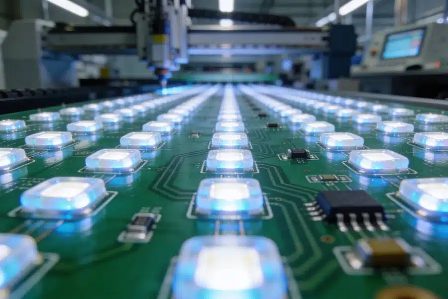
For LED lighting, power modules, motor drives, automotive lighting and inverters, the metal core construction lowers junction temperature, improves light output and component life, and allows higher power density in the same footprint. If the product generates enough heat that temperature limits reliability, a metal core PCB is frequently the difference between a design that works and one that derates.
Electrical Performance: Where CCL Keeps the Lead
Copper clad laminate remains the leader wherever signals matter. Rogers and PTFE laminates deliver controlled, stable dielectric constant and very low loss for RF, microwave, high speed digital, AI server and 5G applications, and multilayer CCL construction supports the impedance control and power integrity that high speed designs demand.
Metal core boards carry current and heat well, but their dielectric is optimized for thermal conduction, not for high frequency stability, and their limited layer count constrains complex routing. Designers who need both heat spreading and high speed signals typically combine the two worlds: a multilayer CCL control board mated to a metal core heatsink plate, a hybrid used widely in automotive and power electronics.
Mechanical and Manufacturing Differences
Mechanically, metal core boards are stiffer, heavier and more resistant to vibration and impact than CCL boards of the same size, and their metal base gives excellent dimensional stability. CCL boards are lighter, easier to route into complex shapes and fully compatible with fine pitch assembly, but they rely on the circuit board thickness for stiffness.
Manufacturing also differs. CCL processing follows the familiar sequence of cutting, drilling, plating, imaging, etching, lamination and finish, with mature yields across every board class. Metal core fabrication adds metal base preparation, high thermal dielectric lamination, CNC machining of the metal and thermal resistance testing, and requires tighter process control, which makes it more demanding and generally more expensive per board.
Cost Comparison in 2026
Price reflects the material and process gap. For copper clad laminate boards, prototype pricing in 2026 typically runs 5 to 20 US dollars for single-sided FR-4 samples, 20 to 80 dollars for double-sided, and 50 to 150 dollars for four layer boards, with small batches at 2 to 10 dollars per board and volume above one thousand boards at 0.5 to 5 dollars per board. Metal core boards cost more at every stage: aluminum base prototypes run 20 to 100 dollars and copper base prototypes 80 to 300 dollars, small batches land at 8 to 30 dollars per board, and volume pricing typically reaches 2 to 15 dollars per board.
The premium is a direct consequence of the metal base, the high thermal dielectric and the extra process steps, and it is justified whenever the alternative would be an expensive thermal management system on a standard board.
Typical Applications
CCL-based boards cover smartphones, laptops, AI servers, industrial controls, medical electronics, communications equipment, automotive ECUs and general consumer products, wherever signals, layers and cost need flexibility. Metal core boards are standard in LED lighting and automotive LED lamps, power modules, motor drives, solar inverters, switch mode power supplies, EV charging systems and high power industrial equipment, wherever watts and temperature define the product.
How to Choose
Choose copper clad laminate when the design emphasizes high speed signal integrity, impedance control, multilayer routing, HDI or broad cost options, or when heat can be handled with vias, planes and airflow. Choose a metal core PCB when the product runs high power continuously, lives in a hot environment, or cannot afford the extra size of a secondary heatsink. And when both requirements exist, plan a hybrid structure from the start so the signal board and the heat spreader are designed together rather than bolted together later.
FAQ
Is a metal core PCB always better than FR-4? No. It is better for heat, but standard CCL materials are better for high speed signals, multilayer density and cost. The right choice depends on the dominant constraint.
Can metal core boards have multiple layers? Yes, but they are usually limited to one to four layers because the dielectric is optimized for thermal conduction and the metal base complicates lamination.
Why are LED boards almost always metal core? LEDs concentrate heat in tiny areas; an aluminum or copper base spreads that heat fast enough to protect the LED and keep light output high.
Choosing a Manufacturer for Both Technologies
Many products need CCL and metal core boards from the same supplier, so factory capability matters. Look for a partner that runs standard and high layer count CCL boards up to sixty layers, supports HDI, rigid-flex, thick copper and ceramic builds, and also processes aluminum and copper base boards with thermal dielectric lamination, CNC metal work and thermal testing. gopcb manufactures multilayer and metal core PCBs under IPC Class 2 and Class 3 programs, with DFM review, prototype service and volume production for LED, power, automotive and industrial customers. Send your stack-up and thermal requirement for a free DFM assessment and a quotation.