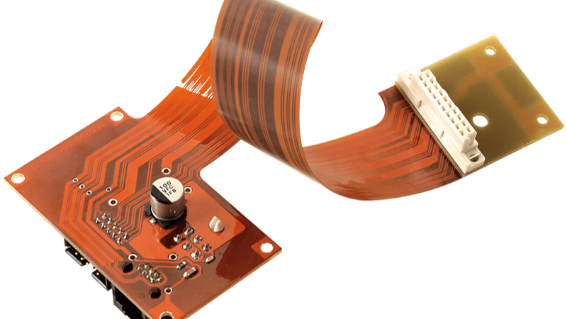
Metal Core PCB: Structure, Materials and Thermal Design
A metal core PCB replaces the usual glass-fibre laminate with a metal plate, and moves the heat-generating components onto that plate through a thin dielectric layer. The change is simple in principle and far reaching in practice, because the base material now carries heat as well as structure, and that changes what the board can do.
What Makes a Metal Core PCB Different
On a conventional board, heat leaves a component through copper, spreads sideways across the plane and then escapes slowly through a poor thermal conductor. A metal core PCB shortens that path dramatically by putting a good conductor directly underneath the component.
The result is a lower thermal resistance from junction to ambient, a more uniform board temperature, and the ability to drive higher power through the same footprint. That is why the technology is standard in LED lighting and common in power conversion.
The Three Layers of the Structure
The stack has three functional layers. The base is the metal plate, usually aluminium, which provides mechanical support and the main heat path. On top of it sits the dielectric layer, a thin, electrically insulating, thermally conductive material that separates the circuit from the metal.
Above the dielectric is the copper circuit layer, patterned and etched like any other single-sided board. A solder mask and legend complete the board. The dielectric layer is the critical element: it must be thin enough to conduct heat and thick enough to withstand the working voltage, which is why its breakdown rating is specified in the datasheet.
Substrate Materials: Aluminum, Copper and Steel
Aluminium is the default. Its thermal conductivity is typically 200 to 250 W/mK depending on alloy, it is light, it is relatively easy to machine, and it costs far less than the alternatives. Most LED boards and a large share of power boards use aluminium.
Copper substrates reach 300 W/mK and above, which matters in very high power density designs, but the material cost and the machining difficulty restrict them to products where performance justifies the premium. Steel appears in a smaller niche, where mechanical strength or magnetic shielding matters more than heat spreading.
Thermal Conductivity in Practice
Substrate conductivity is only part of the answer. The dielectric layer is much less conductive than the metal beneath it, so the total path is dominated by the dielectric thickness and its own conductivity, and by the copper area carrying heat from the component to that dielectric.
In practice this means three design moves: maximise the copper pad under the device, keep the dielectric as thin as the voltage rating allows, and spread the heat over as much metal area as the outline permits. Increasing the metal thickness helps transient performance and mechanical stiffness more than it helps steady-state spreading.
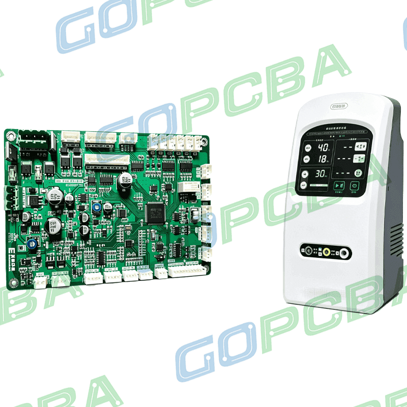
<img src="https://www.gopcba.com/wp-content/uploads/2026/05/彩色多普勒超声驱动PCBA-2.png" alt="Aluminum substrate LED board mounted on a heat sink” />
Fabrication Flow
Manufacturing starts by stacking the dielectric and the copper foil onto the metal plate and laminating them under heat and pressure into a single bonded panel. The copper is then imaged and etched into the circuit pattern using standard processes.
After etching comes drilling for through-holes and mechanical features, surface treatment, solder mask and legend printing, and finally forming and routing to the finished outline. Because the base is metal, cutting and routing use different tooling and generate more wear, which is one reason unit cost is higher than for a comparable laminate board.
Quality Control for Metal Substrates
Inspection covers four properties that are specific to the construction: dimensional accuracy, electrical continuity and isolation, thermal resistance of the assembled stack, and mechanical strength. Thermal cycling is the most informative test, because a dielectric layer that is bonded inconsistently will delaminate or crack after repeated excursions.
X-ray inspection and thermal flow measurements are commonly used together to verify that the dielectric layer is uniform. A board with a thin spot in that layer may pass an electrical test and still fail in the field, so the process control matters as much as the final inspection.
Application: LED Lighting
LED lighting is the largest application, and the reason is straightforward. Light output and lifetime both fall as junction temperature rises, so the metal core board is not only a cooling device but a performance component. A well-designed aluminum substrate board can hold a much larger drive current for the same light output.
LED thermal management on a metal board usually combines a generous copper pad under each emitter, a thin dielectric layer, and a mounting interface that couples the plate to the luminaire body. The interface material and its thickness are as important as the board itself.
Application: Power, Automotive and RF
In power conversion the metal core carries the heat of MOSFETs, diodes and magnetics while providing a mechanically robust base. Automotive electronics use the same structure for LED headlamps, power modules and control units, where vibration and thermal cycling are both severe.
Radio-frequency circuits also benefit, since a metal base provides both a ground reference and a heat path, and its dimensional stability resists the warping that would detune a filter. In all of these cases the design trade is the same: better thermal and mechanical behaviour in exchange for a higher unit cost and a single-sided layout.
Design Limits and Cost
The main limitation is layer count. Because the base is conductive and thick, metal core boards are essentially single-sided for the circuit, with the metal acting as the mechanical and thermal substrate. Multi-layer versions exist but demand additional insulation and careful process control, which raises cost further.
Component density is also lower, since there is no second surface for routing, and placement must be planned around the thermal requirements. That is the price of a thermal path that a laminate board simply cannot match.
Thermal Interface and Board Integration
A metal core board is only as good as the path on both sides of it. Above the dielectric layer, the copper pad under the device determines how much heat enters the board. Below the metal plate, the mounting interface determines how much heat leaves it.
Thermal interface materials are usually the weakest link in that chain. A pad, a dispensing adhesive or a gap filler each add a layer whose thickness and conductivity set the overall resistance, which is why these compounds are specified by thermal performance rather than by mechanical properties alone.
Designing the board to carry current and heat together also changes the copper rules. A supply trace sized only for voltage drop may be too narrow to spread heat effectively, so the same trace width to current calculation should be done with the thermal requirement in mind, and the copper areas around power devices should be deliberately oversized.
Dimensional Stability on a Metal Base
Metal expands differently from the dielectric and copper above it, so every temperature excursion loads the bonded interface. A design that ignores this can pass assembly and still crack after a few hundred thermal cycles in the field.
Keeping the copper balanced across the panel, avoiding large isolated metal areas on one side, and respecting the recommended lamination and curing cycle all reduce that stress. The behaviour of these joints after repeated excursions is part of the wider subject of dimensional stability and expansion.
For assemblies that must survive moisture, salt spray or condensation, the surface finish and any potting and dispensing adhesive applied over the board become part of the thermal design rather than only a protection measure, because both change how heat leaves the surface.
FAQ
Can a metal core PCB have two copper layers? Yes, with an additional dielectric and copper layer on the metal base. It is used for power converters with control circuitry, but the second layer is more expensive and thermally less effective than the layer directly on the metal.
Why is the dielectric layer thickness so important? It is the dominant part of the thermal path and also the electrical insulation. Making it thinner improves heat transfer but lowers the breakdown voltage, so the thickness is chosen to satisfy the safety requirement first.
Is aluminium always the right base material? For most LED and power designs, yes. Copper is justified only where the extra conductivity changes the outcome, and steel only where mechanical or magnetic requirements dominate.