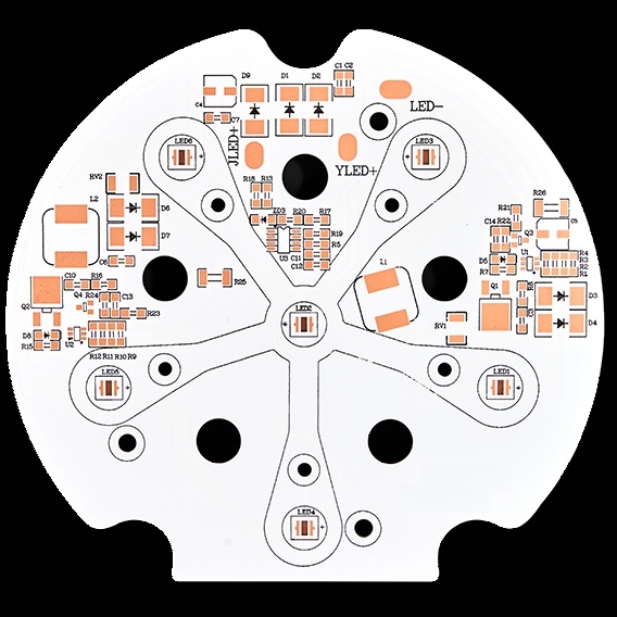
A Metal Core PCB is a printed circuit board designed with a metal substrate or core to provide better thermal performance and mechanical stability than conventional FR-4-based PCBs. Unlike standard PCBs, which typically use FR-4 as the primary structural material, metal core boards use materials such as aluminum, copper, or specialized metal alloys as the heat-spreading core.
The main purpose of a Metal Core PCB is to transfer heat away from heat-generating components more efficiently. This makes metal core technology particularly valuable in applications where thermal performance is critical but the circuit does not necessarily require a highly complex multilayer structure.
Depending on the application, manufacturers can select different core materials, dielectric systems, copper thicknesses, and stackups to achieve the required combination of thermal conductivity, electrical insulation, mechanical strength, weight, and cost.
What Is a Metal Core PCB?
A Metal Core PCB is a circuit board that incorporates a metal substrate beneath an electrically insulating dielectric layer and copper circuit layer. The metal core acts primarily as a heat-spreading and mechanical-support structure.
A typical structure consists of:
Copper Circuit Layer → Dielectric Insulation Layer → Metal Core
The copper layer carries electrical signals and power, while the dielectric layer provides electrical isolation between the copper circuitry and the conductive metal core. The metal core then helps spread and dissipate heat generated by components.
Unlike conventional FR-4 PCBs, which rely heavily on the thermal properties of fiberglass-reinforced epoxy, metal core boards provide a direct and highly effective thermal path through the dielectric layer into the metal substrate.
This structure is particularly useful for power LEDs, power electronics, automotive lighting, motor-control systems, converters, and other applications where excessive heat can negatively affect component performance and service life.
Common Metal Core Materials
The most commonly used materials for metal cores are aluminum and copper. Different materials provide different combinations of thermal conductivity, weight, cost, machinability, and mechanical performance.
Aluminum Core
Aluminum is the most widely used material for Metal Core PCB applications.
Its main advantages include:
- Good thermal conductivity
- Low density and relatively low weight
- Lower material cost than copper
- Good machinability
- Excellent availability
- Good mechanical strength
- Suitable for high-volume manufacturing
Aluminum-core PCBs are especially common in LED lighting because they provide an effective balance between thermal performance, weight, manufacturing cost, and reliability.
For many general-purpose thermal applications, aluminum provides sufficient heat dissipation without the additional cost and weight associated with copper.
Copper Core
Copper offers higher thermal and electrical conductivity than aluminum, making it suitable for applications with particularly demanding thermal requirements.
A Copper Core PCB can provide an efficient thermal path from high-power components into the metal substrate. Copper also offers excellent mechanical properties and dimensional stability.
However, copper has several disadvantages:
- Higher material cost
- Higher density and therefore greater weight
- More difficult machining and processing
- Greater influence on manufacturing cost
For these reasons, copper-core structures are generally selected when their superior thermal or mechanical performance provides a meaningful advantage.
Specialized Metal Alloys
Some applications may use specialized metal alloys or engineered metal substrates to achieve specific mechanical, thermal, or weight requirements.
The appropriate core material should be selected according to the complete application rather than thermal conductivity alone. Factors such as coefficient of thermal expansion (CTE), mechanical strength, corrosion resistance, weight, cost, and manufacturing compatibility should also be considered.
Major Types of Metal Core PCB
Metal core boards can be classified according to their layer structure and thermal architecture. The appropriate configuration depends on circuit complexity, component density, thermal requirements, and manufacturing constraints.
Single-Layer Metal Core PCB
The most common configuration is:
Copper → Dielectric → Metal Core
This structure contains one primary copper circuit layer. The dielectric layer electrically isolates the copper circuit from the metal core while allowing heat to transfer toward the substrate.
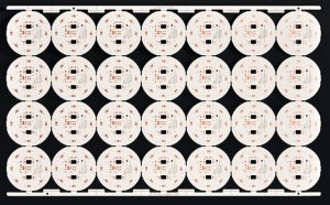
Single-layer Metal Core PCB designs are relatively simple and cost-effective. They are widely used in:
- LED lighting
- Industrial lighting
- Power indicators
- Automotive lighting
- Simple power circuits
- Thermal control modules
Because the structure is simple, it is also easier to manufacture and generally provides a favorable balance between performance and cost.
Thermoelectric Separation Metal Core PCB
Thermoelectric separation structures are designed to improve thermal transfer from high-power components while maintaining electrical isolation between the component pads and the metal substrate.
In high-power LED applications, for example, the thermal path can be designed to minimize the thermal resistance between the LED thermal pad and the metal core.
Copper is often selected for these demanding thermal structures because of its excellent thermal conductivity.
This type of construction can provide significantly better thermal performance than conventional insulated metal substrate designs, but it generally involves more complex manufacturing and tighter process control.
Therefore, it is normally used for high-power applications where the additional cost is justified by thermal requirements.
Double-Layer Metal Core PCB
Double-layer metal core boards can be designed in different configurations depending on whether both sides of the board require circuitry.
One possible structure is:
Copper → Dielectric → Copper → Dielectric → Metal Core
This configuration provides two conductive layers while maintaining electrical isolation from the metal core.
Another configuration is:
Copper → Dielectric → Metal Core → Dielectric → Copper
In this structure, copper circuitry is available on both sides of the metal substrate.
Double-sided configurations provide greater routing flexibility and can support higher component density than basic single-layer metal core boards.
However, manufacturing is more complicated because the metal core affects drilling, registration, lamination, plating, and thermal expansion behavior.
Multilayer Metal Core PCB
For applications requiring greater routing density, manufacturers can integrate additional copper and dielectric layers into a metal-core stackup.
A simplified structure may include:
Signal Layer → Dielectric → Copper Plane → Dielectric → Metal Core
or a more complex multilayer arrangement depending on the design requirements.
Multilayer Metal Core PCB Manufacturing requires careful control of:
- Dielectric thickness
- Thermal resistance
- Layer registration
- Copper thickness
- Lamination pressure and temperature
- CTE mismatch
- Via structure
- Electrical isolation
- Mechanical reliability
It is important to note that multilayer metal core PCBs are technically feasible and can incorporate through vias, blind vias, or other interconnection structures when the construction and manufacturing process support them. However, the presence of the metal core can make interconnection and fabrication more challenging than conventional FR-4 multilayer boards.
As layer count increases, designers must carefully evaluate whether the additional routing capability justifies the increased manufacturing complexity, cost, and thermal considerations.
Advantages of Metal Core PCB
The primary reason for selecting a Metal Core PCB is improved thermal management. However, metal core technology provides several additional benefits.
1. Improved Thermal Management
The biggest advantage of a metal core board is its ability to transfer heat away from components.
Heat generated by LEDs, MOSFETs, power ICs, and other components can travel through the dielectric layer into the metal substrate. The metal core then spreads the heat across a larger area, making it easier to dissipate into the surrounding environment.
Effective thermal management can help:
- Reduce component operating temperature
- Improve long-term reliability
- Reduce thermal stress
- Minimize performance degradation
- Extend component service life
For this reason, Thermal Management is one of the most important considerations when designing a metal core board.
2. Better Mechanical Strength
Metal substrates generally provide greater structural rigidity than many conventional PCB constructions.
This can be beneficial in applications exposed to:
- Mechanical vibration
- Shock
- Temperature cycling
- Repeated thermal expansion and contraction
The actual mechanical performance depends on the metal material, thickness, dielectric system, PCB geometry, and assembly process.
3. Compact Thermal Design
A metal core can reduce the need for large external thermal-management structures in some applications.
Depending on the thermal design, a metal core PCB may reduce reliance on:
- Large heat sinks
- Additional thermal interfaces
- Complex mechanical cooling structures
However, a metal core PCB does not automatically eliminate the need for a heat sink. The final thermal performance depends on the board area, component power, dielectric thermal conductivity, copper distribution, airflow, enclosure design, and ambient temperature.
4. Good Reliability in High-Temperature Applications
By improving heat dissipation, metal core technology can help maintain components within their recommended operating temperature range.
This is particularly important for automotive, industrial, lighting, and power-electronics applications where thermal cycling and elevated operating temperatures can place additional stress on electronic components.
5. Potential for Weight Optimization
Aluminum has a relatively low density compared with copper and can provide an attractive balance between thermal performance and weight.
This makes aluminum-based Metal Core PCB technology particularly useful in applications where thermal performance is required without significantly increasing overall system weight.
Metal Core PCB Manufacturing Process
The manufacturing process depends on the specific stackup and substrate construction, but a typical Metal Core PCB Manufacturing workflow includes several important stages.
1. Engineering and DFM Review
Before production begins, the PCB design should be reviewed for manufacturability.
The engineering team evaluates:
- Layer structure
- Metal core thickness
- Dielectric thickness
- Copper thickness
- Minimum trace and spacing
- Hole sizes
- Thermal vias
- Component placement
- Board dimensions
- Surface finish
- Thermal requirements
A proper DFM review can identify manufacturing risks before fabrication begins.
2. Material Preparation
The metal core, dielectric material, copper foil, and other materials are prepared according to the approved stackup.
Material selection is particularly important because the dielectric must provide both electrical insulation and an efficient thermal path.
3. Circuit Imaging and Etching
The circuit pattern is transferred onto the copper layer through imaging and subsequent etching processes.
The manufacturing parameters must be carefully controlled to achieve the required line width, spacing, copper thickness, and dimensional accuracy.
4. Lamination and Bonding
The copper circuit layer and dielectric material are bonded to the metal core.
Lamination parameters must be controlled carefully because the metal substrate and dielectric material can have different thermal expansion characteristics.
Poor bonding or inappropriate process parameters may lead to delamination, warpage, or thermal-performance problems.
5. Drilling and Via Processing
For boards containing multiple conductive layers, drilling and via formation become important manufacturing steps.
Depending on the construction, manufacturers may use through vias, blind vias, or other interconnection structures.
The presence of a metal core requires specialized process planning because the metal substrate can affect drilling conditions and electrical isolation.
6. Surface Finish
The exposed copper may receive a suitable surface finish, such as:
- HASL
- Lead-free HASL
- ENIG
- OSP
- Immersion tin
The appropriate finish depends on assembly requirements, environmental conditions, cost, and reliability expectations.
7. Electrical Testing and Final Inspection
Finished boards should be inspected for dimensional accuracy, surface quality, insulation performance, electrical continuity, and other specified requirements.
For higher-reliability applications, additional inspection and testing may be required according to the product specification.
Applications of Metal Core PCB
The combination of thermal performance, mechanical strength, and manufacturing flexibility makes metal core technology suitable for a wide range of applications.
LED Lighting
LED lighting is one of the most common applications for Metal Core PCB technology.
LED efficiency and service life can be affected by operating temperature. As LED power increases, thermal management becomes increasingly important.
Aluminum-core PCBs are widely used in:
- Automotive headlights
- LED floodlights
- Street lighting
- High-power spotlights
- Commercial lighting
- Industrial lighting
- LED modules
For extremely high-power LED systems, specialized thermal structures may be considered to further reduce thermal resistance.
Power Electronics
Metal core boards can be used in power electronics where components generate significant heat.
Typical applications include:
- Power converters
- DC-DC converters
- AC-DC power supplies
- MOSFET modules
- Motor-control systems
- Power switching circuits
- Industrial control equipment
The metal substrate helps distribute heat generated by power components across the PCB structure.
Automotive Electronics
Automotive electronics often operate in environments with significant temperature variation, vibration, and limited cooling space.
Metal core PCBs may be used in:
- Automotive lighting
- LED headlamps
- Tail lights
- Motor-control systems
- Power modules
- Battery-related electronics
- Thermal management modules
For automotive applications, designers must consider not only thermal performance but also vibration resistance, temperature cycling, material compatibility, and long-term reliability.
Industrial Equipment
Industrial control and power equipment can generate substantial heat during continuous operation.
Metal core boards can therefore be used in:
- Industrial power supplies
- Motor drives
- Control modules
- Relay systems
- Power switching equipment
- Automation equipment
Consumer and Commercial Electronics
Certain consumer and commercial products also benefit from the thermal performance of metal substrates, especially compact products containing high-power LEDs or power components.
Metal Core PCB vs. FR-4 PCB
The choice between a metal core PCB and a conventional FR-4 PCB depends on the application’s thermal, electrical, mechanical, and cost requirements.
| Feature | Metal Core PCB | FR-4 PCB |
|---|---|---|
| Thermal performance | High, depending on dielectric and metal core | Generally lower |
| Mechanical strength | High | Good |
| Weight | Aluminum core can be relatively light | Generally moderate |
| Circuit complexity | Simple to moderately complex; advanced structures are possible | Excellent for complex multilayer designs |
| Heat dissipation | Excellent for many thermal applications | Usually requires additional thermal solutions |
| Cost | Generally higher than basic FR-4 | Broad range, often economical |
| Common applications | LED, power electronics, automotive | General electronics, computing, communication |
FR-4 remains the preferred material for many complex digital and multilayer circuits. Metal Core PCB technology becomes particularly attractive when thermal management is a primary design requirement.
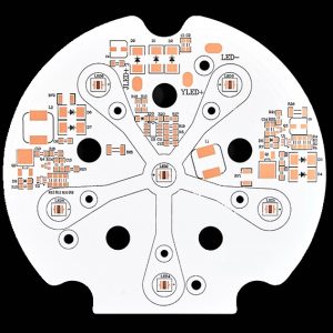
Key Design Considerations for Metal Core PCB
Successful metal core PCB design requires more than simply replacing an FR-4 substrate with a metal substrate.
Thermal Conductivity
The thermal conductivity of the metal core is important, but the dielectric layer is equally critical because it is part of the thermal path.
Designers should evaluate the complete thermal resistance from the component junction to the metal core and ultimately to the surrounding environment.
Dielectric Thickness
A thinner dielectric layer can generally provide a shorter thermal path, but it must still provide sufficient electrical insulation and withstand the required voltage.
The optimum dielectric thickness is therefore a trade-off between thermal performance and electrical reliability.
Copper Thickness
Higher copper thickness can improve current-carrying capability and may also influence heat spreading.
However, thicker copper can increase manufacturing complexity and affect etching, dimensional control, and cost.
Component Placement
High-power components should be positioned strategically to create an efficient thermal path.
Thermally sensitive components should also be considered during layout to prevent excessive heat concentration in localized areas.
CTE and Thermal Cycling
Metal core, dielectric, copper, and component materials can have different coefficients of thermal expansion.
For products exposed to repeated temperature changes, designers should consider CTE compatibility to reduce mechanical stress and improve long-term reliability.
Why Choose Kingda for Metal Core PCB Manufacturing?
Kingda provides PCB manufacturing solutions for projects requiring reliable thermal management, controlled electrical performance, and application-specific construction.
For Metal Core PCB Manufacturing, the correct combination of substrate material, dielectric system, copper thickness, layer structure, surface finish, and manufacturing process is essential.
Kingda can support customers in evaluating PCB construction based on requirements such as:
- Aluminum or copper metal core
- Single-layer and multilayer structures
- Thermal management requirements
- High-current applications
- LED lighting
- Automotive electronics
- Power electronics
- Industrial equipment
- Customized board dimensions and copper thickness
- DFM and manufacturing considerations
Rather than selecting a metal core solely according to thermal conductivity, the complete PCB structure should be evaluated according to operating temperature, power density, electrical isolation, mechanical requirements, production volume, and target cost.
Reliable Engineering and Manufacturing Support
A successful metal core PCB requires close coordination between PCB design and manufacturing.
Kingda focuses on engineering evaluation, manufacturing process control, and application-oriented PCB solutions to help customers develop boards that balance thermal performance, electrical reliability, manufacturability, and cost.
For applications where heat dissipation is a major design challenge, selecting the appropriate Metal Core PCB structure at the beginning of the project can significantly improve overall product performance and reliability.