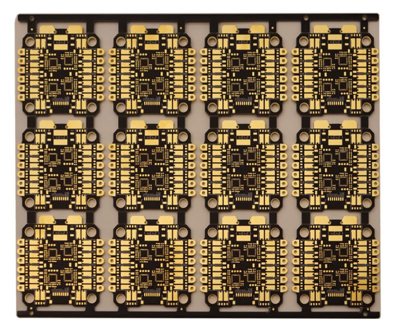
Microcontroller Support Circuitry on a PCB
A microcontroller is a complete computer on one die: a processor, memory for data, non-volatile memory for the program, and interfaces to the outside world. What it is not is a finished circuit. It still needs power, a timebase, a way to be reset, a way to be programmed and a board that keeps all of those quiet.
This article covers the support circuitry that surrounds the device, in the order the datasheet usually presents it, and describes the layout decisions that determine whether the circuit starts reliably every time.
What Is Inside the Package
The program memory is non-volatile, which is why the device runs the same code after the power has been removed and restored. In most modern parts that memory is electrically erasable and is written by an external programmer or by the device itself, but it is still described as read-only memory because the running program cannot overwrite it under normal conditions.
The data memory and the processor are volatile, and they are what the program uses while it is running. Some parts also integrate analogue functions such as an analogue-to-digital converter, a comparator or a digital-to-analogue converter, which changes how the power and ground pins have to be treated because an analogue reference now depends on them.
Power Pins and Decoupling
Every supply pin needs a local decoupling capacitor, placed as close to the pin as the layout allows, with a short connection to the ground reference. A ceramic capacitor of around 0.1 microfarads is the usual value for each pin, and the small size matters less than the short loop from the capacitor to the pin and back to ground.
Where a part has separate analogue and digital supply pins, both need decoupling, and the analogue supply is often fed through a small series element such as a ferrite or a low-value resistor to isolate it from the switching noise on the digital rail. The pin that sets the analogue reference deserves particular care, because any noise on it appears directly in the converted result and cannot be filtered out afterwards.
The Crystal Oscillator Circuit
The oscillator circuit is an amplifier inside the device connected to an external crystal or resonator and two load capacitors. Its frequency depends on the total capacitance seen by the crystal, which includes the two external capacitors plus the stray capacitance of the layout, so the external values are usually chosen slightly below the datasheet figure to allow for the strays.
The layout is the part that goes wrong. The two connections between the crystal and the device pins should be as short as possible, of equal length where the device has separate input and output pins, and surrounded by a ground area that is connected to the device ground. The load capacitors belong next to the crystal, on the same side, with their ground returns taken to the same point. A crystal placed across the board from the device, with long traces, will often start and then fail intermittently or run at the wrong frequency.
Reset Circuit Design
A microcontroller starts when its reset pin is released, and it must be held in reset until the supply has risen far enough for the device to run correctly. The simplest arrangement is a resistor from the pin to the supply with a capacitor to ground, which produces a delay that follows the supply rise; a dedicated supervisory device does the same job with a defined threshold and a guaranteed delay.
Whichever is used, the reset circuit should be treated as a sensitive net. Its connection to the pin should be short, it should not run alongside a switching node, and a small capacitor from the pin directly to the adjacent ground gives the node somewhere to send a fast transient. A reset circuit that works on the bench and resets intermittently in the field is usually a layout problem rather than a component value problem.
The Programming and Debug Interface
The programming interface is a connector or a set of pads that connects the device to a programmer, and it should be placed so that it is accessible without removing other components. The signals it carries are usually a clock, a data line and a reset or a dedicated programming voltage, and the connector needs a ground pin that reaches the device ground by a short path.
Two layout points are worth enforcing. The programming lines should not run across the board from a connector placed at the far edge if a position closer to the device is available, because the longer route adds inductance and makes the interface sensitive to noise during programming. And where the programming pins are shared with application functions, the external circuitry should not load the lines so heavily that the programmer cannot drive them.
Unused Pins and Configuration
An unconnected input pin on a CMOS device is not a harmless pin. It can float to a voltage near the switching threshold, where the input stage draws current and can oscillate, which increases the supply current and injects noise into the device. Unused inputs should be tied to a defined level, either directly or through a resistor, and unused outputs should be left open.
Configuration pins deserve the same treatment. A pin that selects a boot mode, a clock source or a memory width must be tied to the correct level rather than left to an internal default, and the tie should be placed close to the pin with a short connection to ground or supply. Pins that are only read at power-up are easy to forget, and forgetting one produces a board that behaves unexpectedly while every connection is technically present.

Layout Order Around the Device
The layout around a microcontroller is best built in a fixed order. Place the device first, then its decoupling capacitors, then the crystal with its load capacitors, then the reset circuit and the programming connector. Each of these is a small, compact cluster that belongs against the pins it serves, and placing them in this order keeps the sensitive circuitry from being pushed away later.
Once those are fixed, the power supply can be arranged so that its output reaches the device without running across the board, and the general purpose input and output lines can be routed outward. Keeping the switching supply away from the crystal and the analogue supply pins is the single most useful separation on this kind of board, and the layout of a DC-DC converter and its local loop explains how to keep the noise where it belongs.
Ground and Return Path
Everything above depends on a quiet ground. The decoupling capacitors, the crystal load capacitors, the reset capacitor and the programming connector ground should all return to a ground area that is continuous under the device, rather than to separate tracks that wander across the board and share impedance with the supply return.
Where the design includes analogue functions, the ground treatment follows the same principle with a stricter budget, and the guidelines for mixed-signal layout describe how to keep the analogue returns out of the digital current path. A typical microcontroller core board design shows the same arrangement applied to a complete minimum system, which is a useful reference because almost every pin on it has a defined purpose.
FAQ
Why does an unused input pin need to be tied off? Because a floating CMOS input can sit near its switching threshold, where the input stage draws current and may oscillate. Tying it to a defined level removes the current draw and the noise that comes with it.
How close does the crystal have to be to the device? As close as the layout allows, on the same side, with the load capacitors beside it and a ground area around the pair. The exact distance matters less than keeping the traces short and the ground return direct.
Is a dedicated supervisory chip better than an RC reset? It is more predictable, because the threshold and the delay are specified rather than dependent on the supply rise time. On a design with a slow supply ramp or a wide temperature range, the supervisory device is usually worth the extra component.