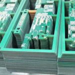
Mixed Alloy Reflow Profile For Backward Compatibility
Not every assembly uses one solder alloy. A board may carry a lead free ball grid array and be soldered with a tin lead paste, or it may carry a leaded component on a lead free board, or it may be assembled with a lead free paste and then repaired with a leaded wire. Each of these is a mixed alloy assembly, and each forces a decision about the temperature at which the whole board will be processed.
This article explains what a mixed alloy joint is, why the profile becomes a compromise, how the profile is designed, what it does to reliability, and how the result is verified.
What Mixed Alloy Assembly Means
A joint is mixed when the solder that forms it comes from more than one alloy. The most common case is a lead free paste with a component whose balls or terminations are leaded, and the reverse also occurs. During reflow the two melt and diffuse into each other, producing a joint whose composition is neither of the originals and whose melting behaviour is therefore different from either.
The distinction matters because the melting range of the mixture can be lower than that of both constituents in some systems and higher in others, and because the amount of mixing depends on how much of each alloy is present and how long the joint is molten. A ball that is only partly melted mixes only at its surface, while a fully molten joint mixes throughout and its properties are those of the resulting alloy.
The Temperature Dilemma
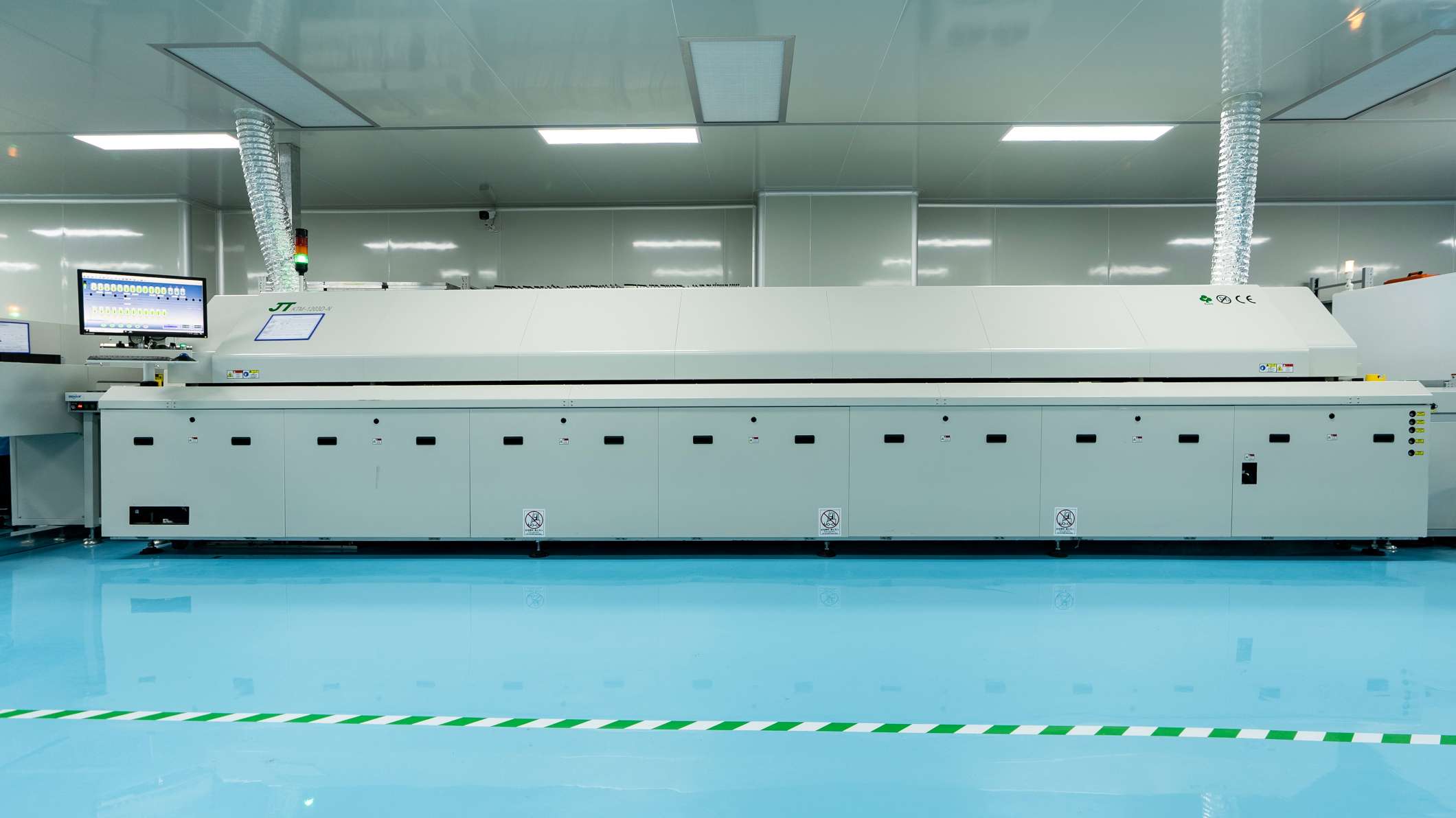
Lead free alloys based on tin silver copper melt at about 217 degrees Celsius, while tin lead eutectic melts at 183 degrees. A board that carries a leaded component with a maximum body temperature of 240 degrees cannot be run on a lead free profile without risk, and a board that carries a lead free ball grid array cannot be reliably joined with a tin lead profile without exceeding the ratings of other parts. The profile therefore has to be designed around the most sensitive device on the board rather than around a standard.
The choice is between three strategies: process the whole board above the lead free melting point and accept the risk to the leaded parts, process it below and accept that the lead free joints do not fully reflow, or use a hybrid in which the lead free joints are formed first and the leaded parts are added in a second, lower temperature operation. Each has a cost, and the decision is normally made from the component list rather than from the process line.
Designing The Profile
Where the board is processed above the lead free melting point, the profile is a conventional lead free one with a soak that allows the smaller joints and the paste to reach temperature together. The leaded components see a higher temperature than they were designed for, and their survival depends on the body size, on the moisture content of the package and on the time above the peak rating. The thermal ratings in the datasheet are the limit, and the profile has to be verified against them rather than against a general rule.
Where the board is processed below the lead free melting point, the lead free joints rely on the paste alloy melting and diffusing into the ball rather than on the ball itself melting. The joint can be electrically sound but its mechanical strength and its resistance to thermal cycling are different from a fully reflowed joint, and the difference is largest where the ball is large relative to the paste volume. That is the case that has to be tested rather than assumed.
What Happens To The Joint
Two things happen at the interface during a mixed reflow. The first is diffusion, which produces a joint whose composition varies across its thickness and whose melting range is therefore not a single value. The second is the growth of intermetallic compounds, which is faster at a higher temperature and is the layer that governs the mechanical behaviour of the joint under thermal cycling.
A mixed joint is not automatically worse than a homogeneous one, but it is less predictable, and the samples that are tested must be made the same way as production. A test vehicle built with the correct paste, the correct ball alloy and the correct profile is the only evidence that means anything; a test of the alloy on its own says nothing about the mixture that will form in the barrel.
Large Bodies And Thermal Mass
The most difficult mixed joints are on large packages, because the ball is big enough that the paste around it contributes only a fraction of the total volume, and because the package acts as a heat sink that keeps the joint from reaching the paste temperature. A large ball grid array on a thick board may need a longer soak and a higher peak than the rest of the assembly, and the profile then has to satisfy both that device and the smallest chip component on the same panel.
Voiding behaves differently in the same conditions, since the flux has a longer path to escape from under a large body, and the mechanisms are described under BGA solder void causes. The sequence as a whole, from paste selection to the final inspection, is covered under PCBA development process.
Verification And Documentation
Verification is by inspection of the joint and by test of the assembly. X-ray shows the shape of the joint and the voiding, a cross section shows whether the ball melted and how far the diffusion progressed, and a thermal cycle test shows whether the joint survives the conditions the product will see. The three answer different questions, and a mixed alloy process is normally qualified with all three.
The documentation then has to record what was actually used, because a mixed assembly is defined by its history rather than by its drawing. Which alloy was on the component, which paste was used, which profile was run and which repair alloy was permitted all belong in the process record. Without that record, the alloy in a joint cannot be reconstructed later, and a field failure cannot be compared with the qualification test. The alloy choice and its consequences are also discussed under lead free versus leaded solder and under PCB design and fabrication.
Additional Considerations for This Build
Practical attention to backward compatibility pays for itself here, because it decides whether the finished board behaves as the drawing intended. Where the requirement is not stated on the fabrication drawing or in the assembly notes, the shop has to assume a default, and that default is rarely the value the design was simulated with. Stating backward compatibility explicitly, together with the tolerance that applies, removes the assumption and keeps the result predictable from batch to batch.
Deliberate attention to peak temperature pays for itself here, because it decides whether the finished board behaves as the drawing intended. Where the requirement is not stated on the fabrication drawing or in the assembly notes, the shop has to assume a default, and that default is rarely the value the design was simulated with. Stating peak temperature explicitly, together with the tolerance that applies, removes the assumption and keeps the result predictable from batch to batch.
FAQ
Is a mixed joint legal under the restrictions on lead? The restriction applies to the product and to its exemptions rather than to the process, so the question is whether the finished product complies. A mixed process used for a repair does not by itself change the status of the product.
Can a leaded ball be reflowed on a lead free profile? It can, if the component ratings allow the temperature and the exposure time. The risk is to the package and to the other parts on the same board, not to the ball itself.
How is a mixed joint identified after the fact? By a cross section and an elemental analysis of the joint, which shows the composition gradient. Visual inspection cannot tell a mixed joint from a homogeneous one.