Mixed Technology PCBA Assembly
Most production boards carry both surface mount and through-hole components, and that combination is called mixed technology. It is not a compromise but a deliberate arrangement, and the reason it persists is that each family does something the other cannot. What matters for assembly is the sequence, because the two are soldered by different processes.
Why the Combination Exists
Surface mount parts are small, cheap and suited to automation, and they allow both sides of the board to be populated. Through-hole parts provide joints that resist mechanical load, and they suit components with mass, with significant heat dissipation or with a requirement to be inserted and removed repeatedly.
A design that uses both is choosing each for what it does best. The cost is an additional process step, and managing that step is what mixed technology assembly is about. Our PCBA soldering requirements article covers the joint standards that apply to each type.
The Soldering Sequence
Surface mount parts are placed and reflowed first, because reflow is a whole board process that heats everything. Through-hole parts are inserted afterwards, because their leads pass through the board and would obstruct the printing and placement of the surface mount side.
Where components are fitted on both sides, the sequence is: print and place side one, reflow, print and place side two, reflow again, then insert and solder the through-hole parts. Each additional pass heats the assembly again, which is why the number of passes belongs in the material and profile decisions. Our high Tg material article describes how the laminate responds to repeated exposure.

Wave Soldering and Its Constraints
Wave soldering passes the board over a standing wave of molten solder, which contacts the underside and fills the joints of every through-hole lead at once. It is fast and suits boards with many through-hole joints.
The constraint is that the wave also contacts every exposed surface on the underside. Surface mount parts already placed there may be washed off or damaged, so wave soldering suits designs where the through-hole parts are on the top and the underside is clear, or where the underside parts are protected by adhesive. The orientation of the board through the wave also matters, because the solder must reach each joint in turn without shadowing.
<img src="https://www.gopcba.com/wp-content/uploads/2020/12/work-overlay.png" alt="selective soldering nozzle applying solder to a through-hole joint” />
Selective Soldering
Selective soldering applies solder to one joint or one group at a time using a small nozzle, with the rest of the assembly unaffected. It allows through-hole parts to be soldered on a board that already has surface mount parts on both sides.
It is slower than wave soldering per joint, and it is the process that makes dense mixed technology assemblies possible. The nozzle size must match the joint, the thermal profile must heat the barrel without overheating the neighbouring components, and the flux must be applied precisely.
Hand Soldering Where Neither Fits
A small number of joints are still soldered by hand. Connectors that cannot tolerate the heat of a wave, parts inserted after the main process, and rework all fall into this category.
Hand soldering depends on operator skill and on having the right iron, tip and alloy for the joint. Its quality is variable, which is why designs should minimise the number of hand soldered joints and why those that remain should be inspected. The joint standard is the same as for any other process; only the method differs.
Process Control Across Two Processes
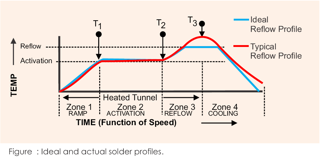
Mixed technology assembly means two profiles, two sets of parameters and two sets of records. The reflow profile covers the surface mount stage; the wave or selective profile covers the through-hole stage.
Both should be recorded for the build, and the second must account for the fact that the board has already been through the first. A profile that would be correct on a bare board may overheat a component that has already seen one reflow cycle. Our PCB quality article describes the records that make this traceable.
Design Choices That Simplify Assembly
The design controls how difficult the second soldering operation becomes. The following decisions reduce the number of process steps and the risk attached to each of them:
- Group through-hole parts on one side and in one area so a single soldering operation covers them.
- Keep through-hole joints away from fine pitch surface mount parts that could be damaged by heat.
- Check whether the part is available in a surface mount package before specifying a through-hole version.
- Confirm the board orientation through the wave and the resulting shadowing of joints behind tall parts.
- Provide thermal relief on plane connections so the barrel can reach soldering temperature.
- Allow enough pad size for a proper fillet on both sides of the board.
- Avoid placing a connector where its body obstructs access to nearby through-hole joints.
- State on the assembly drawing which joints are wave, selective and hand soldered.
- Record the number of reflow passes the assembly will see and confirm the components tolerate it.
- Identify any part that must be inserted after soldering so that the sequence can be planned.
Each of these is a layout decision with a process consequence, and taking them into account before release avoids a build that has to be re-planned on the line. Our layout notes cover the placement side of the same problem.
Inspecting a Mixed Technology Joint
The two joint types fail differently, and the inspection method has to cover both. Surface joints fail as insufficient solder, bridging or tombstoning, all of which are visible from above. Through-hole joints fail as insufficient barrel fill or as voids inside the barrel, which are not visible from the surface at all.
Automated optical inspection therefore covers the surface joints efficiently, while barrel fill requires X-ray sampling or periodic cross sectioning. Planning both from the start prevents the situation where the through-hole joints are assumed to be good because nothing visible is wrong. Our electrical test coverage notes describe how the two methods complement each other.
Where the assembly will see thermal cycling in service, the through-hole joints are often the ones that survive longest, because the lead absorbs movement that a flat joint would have to resist. That is one of the reasons the mixed technology construction remains common in products that must be durable rather than merely cheap. Our component tolerance and reliability article describes the mechanism.
FAQ
Is mixed technology assembly more expensive? It involves an additional soldering operation, so it costs more than an all surface mount design. The premium is small when the through-hole parts are few and grouped.
Can wave soldering be used with parts on both sides? Only where the underside parts are protected or omitted. Selective soldering is used where the underside is populated.
How many reflow passes can a board tolerate? It depends on the components and on the laminate. Each pass adds thermal exposure, and the profile for later passes should be adjusted for parts already soldered.
Should through-hole parts be avoided in new designs? They should be chosen on their mechanical and thermal merits rather than by default. Where a surface mount part meets the requirement, it is simpler to assemble.
What is the most common mixed technology defect? Insufficient barrel fill in the through-hole joints, which is difficult to see and requires a profile or flux correction rather than rework.