PCBA Soldering Requirements for the PCB Design
Soldering does not begin at the assembly house; it begins with the board design. Heat resistance, board shape, edge clearance, fiducial marks and panelization all have to be correct before the first board reaches the paste printer. When they are not, the line compensates with slower settings, manual handling and rework, and the result shows up as defects rather than as a message to the designer. PCBA soldering requirements are therefore best treated as design inputs.
Heat Resistance and the Lead-Free Window
Lead-free assembly pushes reflow temperatures higher. A typical lead-free profile holds the board above 217 degrees Celsius for 30 to 65 seconds, with a peak between 235 and 245 degrees. The laminate therefore has to survive a short excursion at 260 degrees for 10 seconds without blistering, delamination or loss of dimensional stability. High glass transition temperature material with a decomposition temperature well above the profile peak is the baseline, and thin boards or unusually large panels deserve an extra check because they absorb heat differently.
Heat resistance is not only about the laminate. Solder mask adhesion, silkscreen and the surface finish all see the same temperature, and a finish that oxidizes badly in the oven will produce poor joints no matter how good the paste is.
Board Shape and Aspect Ratio
A rectangular outline with a length-to-width ratio of about 3:2 or 4:3 handles best on a conveyor. Long, narrow boards sag in the middle at reflow temperature, and a warped board causes placement offset, uneven paste release and, in the worst case, components that shift or tombstone. When the product requires a long outline, the panel should be designed to support it and the assembly house should know before the order is placed.
Standardizing dimensions pays off across the whole flow. A board that matches a panel size the line already runs needs fewer changes to conveyor settings and fixtures, and the tooling cost is spread across the build. Outline and mounting features should be defined with the same care as the circuit, as described in these board outline and mounting design notes.
Size Limits of the Placement Equipment
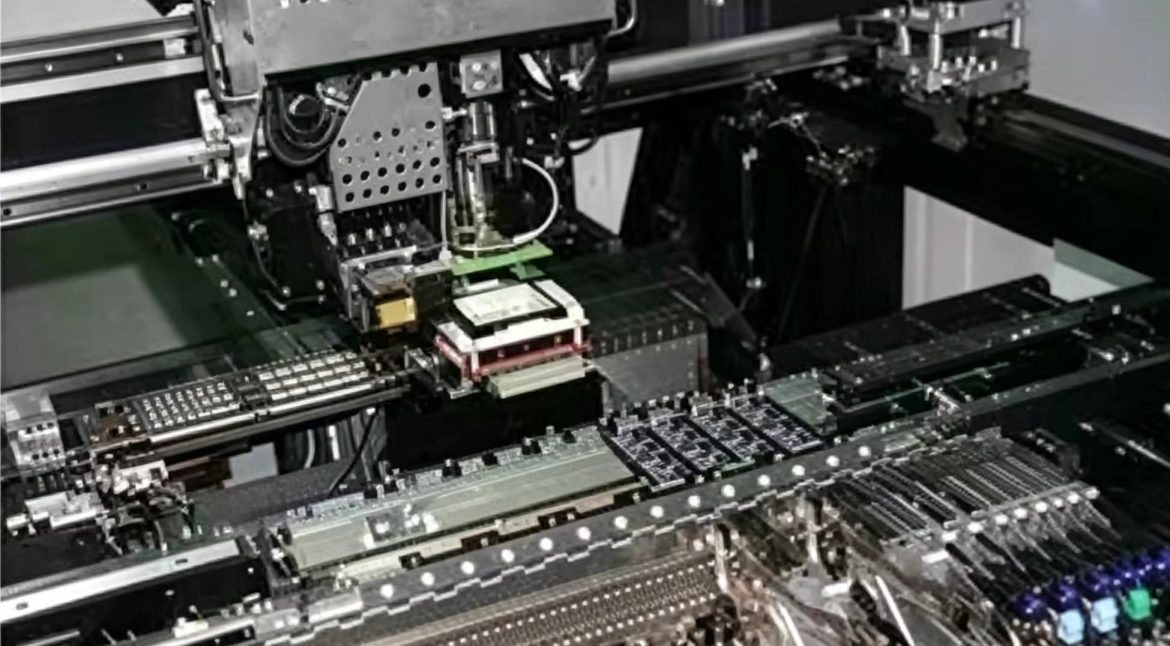
Each machine has a minimum and a maximum board size. A common working range is 50 by 50 mm at the small end and about 400 by 460 mm at the large end, and a board outside that range has to be panelized or handled manually. The size also determines how many boards fit on a panel, which affects the effective placement rate and the cost per unit.
Small boards are usually combined into a panel with breakaway tabs or V-score. The panel must still fit the machine, and the individual boards must separate cleanly without stressing nearby components.
Between the board and the machine there is the transport system, and the interfaces to it are purely geometric.
Process Edge and Rail Clearance
The conveyor grips the board along its long edges. A 5 mm strip on each of those edges must be kept clear of components so the rail has something to hold, and where the product cannot spare the space, a process edge has to be added and broken off after assembly. For boards that pass over a wave solder pot, the short edges usually need about 3 mm of clearance to prevent solder from climbing onto the surface.
Components placed inside the rail zone interfere with clamping, and no machine setting can compensate. Keep-outs on the process edge should be marked in the assembly drawing so the restriction survives the next design revision.
Fiducial Marks
A fiducial mark is a copper dot that gives every machine in the line a shared reference. The standard pattern is a 1 mm copper pad with a clear area about 3 mm across around it, with strong contrast between the metal and the surrounding laminate. Inside that 3 mm circle there should be no silkscreen, no other pad and no V-score, because any of them will confuse the vision system.
Fiducials are placed on the panel and, for fine-pitch work, locally next to the dense package where the global reference is not accurate enough. Global marks are usually three per panel; local marks are added where the pin pitch is 0.5 mm or less. Missing or poorly contrasted fiducials are one of the most common reasons a build starts late.
Panelization
Boards smaller than roughly 50 by 50 mm are normally panelized. V-score, stamp holes and routed slots are the usual separation methods, and each has a different effect on the board edge and on the process. V-score is fast and inexpensive but leaves a small amount of material and cannot follow a curved outline; stamp holes leave a rougher edge but allow complex shapes.
The panel must be sized for the machine, and the separation method must be compatible with the components near the edge. A board separated by V-score has to tolerate the bending force applied during depanelization, and brittle parts close to the score line will crack. Deciding the panel layout together with placement order and pad positioning avoids that conflict.
The last group of requirements concerns what happens after soldering, when flux residues are removed and the assembly is inspected.
Solvent and Cleaning Compatibility
Rosin-based flux residues are normally cleaned with a solvent or a saponifier, and the board has to withstand the process. The solder mask must not soften, blister or turn white, the silkscreen must stay legible, and any exposed laminate must resist absorption. Where cleaning is not possible, a no-clean process with a compatible flux is the alternative, but the assembly house should confirm that residues are acceptable for the product environment.
Cleaning decisions belong in the documentation rather than in the operator’s judgement, because the choice affects the flux specified in the BOM and the process settings in the reflow profile.
Design for Manufacturability Checks
Most of these requirements can be verified automatically. Fabricators and assemblers offer DFM reports that flag narrow solder mask dams, pads too close to the board edge, missing fiducials and components inside the rail zone. Reading that report before the order is confirmed is faster than discovering the problem when the line stops, and the wider set of PCB design guidelines for manufacturability covers the layout side of the same checks.
The practical test of a design is whether the assembly house can run it with standard settings. Every exception adds handling, and handling adds variation.
FAQ
How much clearance do I need along the board edge? Allow 5 mm of component-free space on the long edges for conveyor clamping, and about 3 mm on the short edges if the board passes over a wave solder pot. If the product cannot spare the space, add a breakaway process edge.
What temperature must the laminate withstand? A common requirement is 260 degrees Celsius for 10 seconds, which covers a lead-free reflow excursion above 217 degrees for 30 to 65 seconds. Thin and large boards need extra evaluation because they heat unevenly.
Can fiducials be placed on the finished board rather than the panel? They can, and they often are, but at least three global marks per panel are still needed for the machines that handle the panel before depanelization.