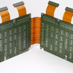
Multilayer PCB Stackup Rules: Planes, Signals and Symmetry
Layer assignment is the first decision that constrains everything after it. Once the stack is fixed, the reference planes available to each routing layer, the impedance targets and the symmetry of the build are all determined, and changing them later means restarting the layout. A few rules cover most of what a prototype stack needs to get right, and they apply whether the board has four layers or twenty. This article sets out the multilayer PCB stackup rules that matter most in practice.
How many layers, and why the count is flexible
Boards range from single-sided through double-sided to multilayer, and in principle the layer count is unlimited, with production boards exceeding a hundred layers. In practice four and six layers cover the majority of designs. A simple four-layer board adds a power plane and a ground plane to the two routing layers of a double-sided board, which solves a large part of the electromagnetic interference problem, improves system reliability, raises routing completion and allows a smaller board for the same circuit. The count should follow the function: enough layers to give every high-speed net a reference plane and every power net a low-impedance path, and no more than that, because each additional pair adds cost and lamination risk.
Keep the power plane coupled to the ground plane
The power plane should sit close to the ground plane so the two are tightly coupled, and it should be placed below the ground plane rather than above it. Tight coupling between the two planes creates a low-impedance path for high-frequency currents and turns the plane pair into an effective distributed capacitance, which helps at frequencies where bulk capacitors have already become inductive. The spacing between them is a stack decision with a direct electrical consequence, so it should be chosen deliberately and recorded rather than left at a default. Where a power plane has to be split between voltage rails, keep the return path in mind: a signal that crosses a split in its reference plane has no continuous return path directly beneath it.
Put a ground plane under the component layer
The layer immediately below the component side should be a ground plane. It shields the components from the routing beneath, and it provides a continuous reference for the traces on the top layer. A signal that runs over a solid ground plane has a well-defined return current directly beneath the trace, which controls loop area and therefore radiation and crosstalk. Remove that plane and the return current finds its own path, usually a longer one that couples into whatever it passes. The same logic applies at the bottom of the stack: the layer above the secondary component side is a good place for the second ground plane.

Keep signal layers next to planes
Every signal layer should be adjacent to an internal plane layer, not directly adjacent to another signal layer. Two routing layers pressed together share a single dielectric with no reference between them, so the coupling between them is uncontrolled and crosstalk rises quickly. A signal layer next to a ground plane is a microstrip, and a signal layer between two planes is a stripline, both of which have predictable impedance and controlled coupling. Where the layer count forces adjacent signal layers, route the sensitive nets on the side facing the plane and keep the two signal layers orthogonal so that any coupling is between traces crossing at right angles rather than running parallel. The general aim is that every signal layer is as close to a ground plane as the build allows.

Separate digital and analog circuitry
Mixed-signal boards need digital and analog sections kept apart. Where the layer count permits, place analog signal traces and digital signal traces on separate layers, and shield them from each other. Where they must share a signal layer, use an isolation band or ground traces between the two regions and keep the return currents from crossing into the other domain. The power and ground for the analog section must be separate from the digital supply and must not be mixed; a shared plane couples switching noise directly into the analog reference, and no amount of filtering at the device pin recovers the lost accuracy. Tie the two grounds at a single defined point, chosen so that digital return currents do not flow through the analog region. The ground routing and power trace planning decisions follow directly from this split.
Keep the stack symmetric
Layers should be arranged symmetrically about the centre of the stack, and an even number of copper layers is preferable to an odd number. Layer symmetry is not an aesthetic preference: the panel sees pressure and heat during lamination, and residual stress remains in the finished board. If the two halves of the stack are not balanced, the stress on one side differs from the other and the board bows. An odd number of copper layers usually means an unbalanced stack, or a stack where one side uses a much thicker dielectric to compensate, and both outcomes are harder to control. If the function genuinely requires an odd count, balance the copper distribution and the dielectric thickness around the centre, and confirm the approach with the fabricator. Record layer symmetry on the stack drawing, because it is easy to verify and equally easy to lose between design revisions. The reasoning behind balanced stack-ups with an odd layer count applies to every build, not only the unusual ones.
What the rules buy
A stack that follows these rules delivers high assembly density in a small volume, shorter interconnections between devices, faster signal transmission, easier routing and effective shielding. Those benefits come from the plane structure rather than from the layer count alone, which is why adding layers without giving each signal layer a reference plane improves nothing. gopcb reviews the proposed stack against the routing plan before the inner layers are released, so that plane splits, reference continuity and symmetry are settled while a change is still free.
Two practical checks close the review. Confirm the dielectric thicknesses and the copper weights against the impedance targets for every controlled net, and confirm that the drill and via structure suits the thickness of the finished board. A stack that looks correct on paper can still fail if the aspect ratio is beyond what the plating line can hold, so the mechanical and electrical reviews belong together.
FAQ
Should I always use an even number of layers? An even count makes symmetry easy and is preferred for that reason. An odd count can work if the copper distribution and dielectric thickness are balanced about the centre, but it requires more care and should be confirmed with the fabricator.
Why must a signal layer be next to a plane? The plane gives the trace a defined return path immediately beneath it, which controls loop area, impedance and crosstalk. Two signal layers pressed together have no reference between them, so coupling between them is uncontrolled.
Can analog and digital share a ground plane? They should not share one without a defined split and a single tie point. Digital return currents are rich in switching noise, and letting them flow through the analog reference couples that noise directly into sensitive measurements.