Outdoor gateways serve as edge IoT devices for data acquisition, processing, and communication. They are often installed in outdoor cabinets and exposed to demanding environmental conditions, including wide temperature fluctuations, high humidity, condensation, lightning-induced surges, and the coexistence of digital and RF signals.
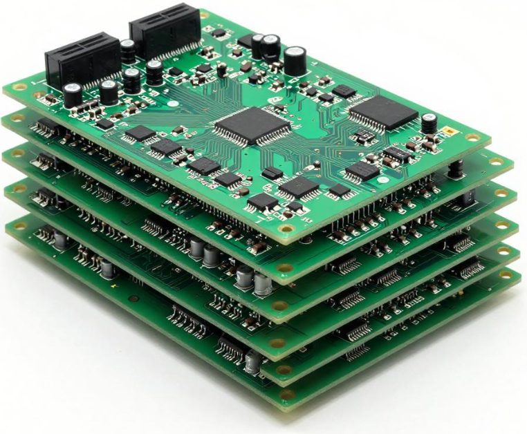
Compared with four-layer boards, a 6-layer PCB provides more flexibility for separating power, ground, high-speed signals, and RF circuits. However, simply copying a six-layer stackup used in an indoor router does not guarantee reliable outdoor operation. Temperature and humidity variations can change material properties, mechanical dimensions, and electrical characteristics, potentially leading to impedance drift, EMC issues, warpage, or interlayer reliability problems.
For this reason, an outdoor gateway requires a PCB stackup that considers electrical performance, thermal cycling, environmental reliability, and manufacturing capability at the same time.
1. Start With the Right 6-Layer PCB Stackup
Two common six-layer structures are:
- Top Signal – GND1 – Power1 – Power2 – GND2 – Bottom Signal
- Top – GND1 – Signal – Power – GND2 – Bottom
For many outdoor gateway designs, the first structure can provide a practical starting point because the outer signal layers are directly adjacent to continuous ground reference planes.
With this arrangement, high-speed DDR interfaces and RF signals routed on the outer layers can maintain a relatively short and predictable return path. A continuous reference plane also helps reduce current-loop area and can support EMC design by limiting unwanted electromagnetic coupling.
The two internal power layers can be assigned to different power domains, such as 12 V input, 5 V, 3.3 V, and RF supply rails. When the power and ground planes are closely coupled, their distributed capacitance can also contribute to power-distribution-network performance.
However, the stackup should not be selected solely because it is a “classic” six-layer structure. The actual power domains, high-speed interfaces, RF routing requirements, isolation requirements, and connector locations should be considered before finalizing the layer assignment.
2. Select Materials for Outdoor Environmental Conditions
Material selection is one of the most important factors in PCB reliability for outdoor gateways.
A standard FR-4 material can be suitable for many applications, but outdoor equipment may require higher thermal and environmental margins. High-Tg FR-4 materials are often considered when the board must withstand repeated thermal exposure, especially when the product operates across a wide temperature range.
Rather than specifying one Tg value for every design, engineers should evaluate:
- Tg and decomposition temperature (Td)
- Z-axis CTE
- Moisture absorption
- Dimensional stability
- Lamination compatibility
- CAF resistance where applicable
- Dielectric-property stability over temperature and frequency
- Copper-to-laminate and solder-mask adhesion
A high-Tg material alone does not guarantee long-term reliability. Material selection must be combined with an appropriate lamination process, stackup design, copper distribution, and environmental validation.
For gateways incorporating Sub-G, 5G, or other RF modules, dielectric stability is particularly important. Changes in dielectric constant with temperature and moisture can affect transmission-line impedance and RF phase characteristics. Therefore, RF material data should be evaluated at the actual operating frequency and relevant environmental conditions rather than relying only on room-temperature nominal values.
3. Consider Board Thickness and Mechanical Stability
A 1.6 mm finished board thickness is a common starting point for many six-layer gateway designs because it provides a useful balance among mechanical stiffness, routing space, component compatibility, and manufacturing availability.
However, board thickness should not be treated as a universal requirement. The appropriate thickness depends on board dimensions, connector loads, component density, enclosure constraints, copper distribution, and mechanical requirements.
For outdoor equipment, mechanical stability becomes particularly important because repeated heating and cooling can cause dimensional changes and stress accumulation. A poorly balanced multilayer structure may experience warpage during manufacturing or environmental cycling.
Engineers should therefore evaluate not only nominal board thickness but also:
- Finished-board thickness tolerance
- Layer-to-layer dielectric thickness
- Copper distribution
- Symmetry of the stackup
- Lamination structure
- Board outline and cutouts
- Connector and mounting-hole locations
- Expected mechanical loads
These factors are directly related to long-term PCB reliability.
4. Control Dielectric Thickness for Impedance Stability
In high-speed and RF designs, dielectric thickness is one of the key parameters affecting controlled impedance.
For a transmission line, impedance is influenced by trace width, copper thickness, dielectric thickness, dielectric constant, and the geometry of the reference plane. Therefore, the stackup cannot be separated from impedance control.
For example, a microstrip on an outer layer and a stripline between internal reference planes will have different field distributions and impedance characteristics. The final impedance must be calculated using the actual stackup rather than a nominal material thickness alone.
For outdoor gateways, the design should also consider variations caused by:
- Lamination compression
- Resin content and resin flow
- Glass-weave distribution
- Copper thickness tolerance
- Copper surface roughness
- Material Dk variation
- Temperature
- Moisture absorption
- Manufacturing tolerances
A board that passes impedance testing at room temperature may still require additional validation if the product specification covers a wide environmental range. For critical RF and high-speed channels, temperature-dependent material data and prototype measurements can be used to establish an appropriate impedance margin.
5. Design the Stackup Around Signal Return Paths
A good stackup is not simply a collection of signal, power, and ground layers. The relationship between each signal layer and its reference plane is equally important.
High-speed DDR signals should have a continuous reference plane and a controlled return path. RF traces should also maintain a stable electromagnetic environment along the entire routing path.
When a signal changes layers through a via, the return current may need to transition between reference planes. If the transition is not properly designed, additional inductance and impedance discontinuity can be introduced.
Ground stitching vias can help provide a lower-inductance return path around certain layer transitions, RF structures, connectors, and board edges. Their number and spacing, however, should be determined according to the actual frequency range, stackup, via geometry, and EMC requirements rather than applying one universal spacing rule.
6. Separate Power, RF, and High-Speed Digital Circuits
Outdoor gateways commonly integrate multiple functional blocks, including:
- DC power conversion
- DDR or other high-speed memory interfaces
- Ethernet
- MCU or processor circuits
- Sub-G or cellular RF
- GNSS
- Sensor interfaces
- Protection and surge circuits
These circuits should be assigned appropriate physical regions while maintaining continuous reference planes.
High-current switching loops should be kept away from sensitive RF and clock circuits. DC/DC converter nodes can generate strong transient fields and common-mode noise, while RF circuits are sensitive to unwanted coupling.
A practical layout strategy is to define functional regions first, then determine signal routing, power-plane distribution, and grounding connections. This prevents the stackup from becoming disconnected from the actual PCB layout.
7. Copper Thickness Must Balance Current and Manufacturing Capability
Copper thickness should be selected according to actual current requirements rather than simply increasing copper thickness throughout the entire board.
For example, a gateway may use thinner copper for low-current digital and RF circuits while using thicker copper or larger copper areas for power-input and regulator regions.
When a power layer uses heavier copper, engineers should consider:
- Current density
- Temperature rise
- Trace width
- Via current sharing
- Copper-plane distribution
- Heat dissipation
- Etching capability
- Minimum spacing
- Lamination behavior
Increasing copper thickness can improve current-carrying capability, but excessive copper can also make fine-line fabrication more difficult and affect resin distribution during lamination.
Therefore, copper thickness should be optimized together with PCB manufacturing capability.
8. Validate the Stackup Under Real Environmental Conditions
For an outdoor gateway, room-temperature electrical testing is only part of the verification process.
A more complete validation plan can include:
- Stackup verification
Confirm actual dielectric thickness, copper thickness, material construction, and layer-to-layer geometry. - Impedance testing
Use TDR or another appropriate method to verify critical single-ended and differential transmission lines. - Thermal cycling
Expose representative boards to the specified temperature range and cycling profile. - Humidity and moisture testing
Evaluate the influence of moisture on insulation, material properties, solderability, and RF performance where relevant. - EMC/EMI testing
Check conducted and radiated emissions under representative operating conditions. - Cross-section analysis
Inspect plated holes, dielectric interfaces, copper thickness, resin distribution, and potential cracks or delamination. - RF performance verification
Measure insertion loss, return loss, phase behavior, and other application-specific RF parameters before and after environmental exposure.
The exact test conditions should be defined according to the product specification, applicable standards, operating environment, and reliability targets.
9. Common Stackup Selection Mistakes
Several mistakes frequently appear when developing outdoor gateway PCBs:
Copying an indoor router stackup directly
Indoor products may have a narrower environmental range and different EMC requirements. Outdoor equipment requires additional consideration of temperature, humidity, condensation, and mechanical stress.
Focusing only on nominal Tg
A higher Tg does not automatically mean better overall reliability. Z-axis CTE, Td, moisture absorption, modulus, adhesion, and process compatibility can also be important.
Using room-temperature Dk for the entire design
For RF and high-speed channels, temperature and frequency dependence can affect the actual electrical behavior.
Ignoring the return path during layer transitions
A signal via without an appropriate reference-plane transition can introduce additional inductance and common-mode conversion.
Increasing copper thickness everywhere
Heavy copper can improve power handling but may reduce routing density and increase manufacturing difficulty.
Treating impedance testing as a one-time prototype activity
Production variation in dielectric thickness, copper thickness, etching, and lamination can affect final impedance. The impedance specification should therefore be connected to the PCB manufacturing inspection process.
10. Recommended Development Workflow
A practical outdoor gateway stackup development workflow is:
Step 1: Define electrical requirements
Identify DDR, Ethernet, RF, clock, power, and sensitive analog interfaces.
Step 2: Define environmental requirements
Determine operating temperature, storage temperature, humidity, condensation exposure, and expected thermal cycling.
Step 3: Select materials
Compare high-Tg FR-4 or other suitable materials according to thermal, dielectric, moisture, and reliability requirements.
Step 4: Build the stackup
Define signal, ground, and power layers while maintaining suitable reference-plane relationships.
Step 5: Calculate controlled impedance
Use actual copper thickness, dielectric thickness, Dk, trace geometry, and manufacturing tolerances.
Step 6: Perform SI/EMC review
Check return paths, plane continuity, RF isolation, power-loop coupling, and potential radiation paths.
Step 7: Conduct DFM review
Verify that the stackup can be manufactured consistently with the selected materials, copper thicknesses, line widths, spacing, vias, and lamination process.
Step 8: Validate prototypes
Combine electrical testing with thermal cycling, humidity exposure, EMC testing, and physical failure analysis where required.
Conclusion
An outdoor gateway 6-layer PCB should not be designed by simply copying a conventional indoor networking-board template. The stackup needs to balance high-speed signal integrity, RF performance, power distribution, thermal behavior, mechanical stability, and environmental durability.
A structure such as Top Signal – GND1 – Power1 – Power2 – GND2 – Bottom Signal can provide a useful starting point for many designs, but the final architecture must be verified against the actual circuit, material system, impedance requirements, environmental conditions, and manufacturing capability.
By combining appropriate high-Tg materials, continuous reference planes, controlled dielectric thickness, optimized copper distribution, reliable return paths, and environmental validation, engineers can establish a more robust PCB stackup for long-term outdoor operation.
Kingda can support outdoor gateway PCB development with stackup evaluation, material selection, impedance control, DFM review, prototype verification, and volume PCB manufacturing, helping engineers translate electrical and environmental requirements into a manufacturable PCB design.