Package Substrate Selection For IC Assembly
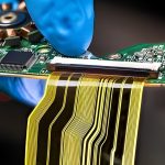
A package substrate is the small high density board inside an integrated circuit package that carries the die on one side and the solder balls on the other. It is a printed circuit board in every respect except scale: its lines are a few micrometres wide, its vias are formed by laser, and its tolerances are measured in micrometres rather than in millimetres.
This article covers what the substrate has to do, how core and coreless builds differ, how warpage is managed, and how the material is chosen.
What The Substrate Has To Do
The substrate performs four functions at once. It provides a fine pitch footprint for the die, it redistributes the die connections to a coarser pitch for the balls, it carries power from the balls to the die with a low impedance, and it provides a mechanical base that survives the assembly processes. It also has to match the expansion of the die closely enough that the die attach and the underfill are not overstressed during thermal cycling.
Those requirements conflict. Fine lines and many layers reduce the space available for power distribution, and a stiff substrate that resists warpage is also one that imposes more stress on the die. The design is a balance, and the balance is different for a processor, a memory device and a power device. The general principles of high density construction apply here as much as on a larger board, as described under blind and buried via stack selection.
Core And Coreless Builds
A cored substrate has a rigid centre layer, usually a glass reinforced epoxy, with build-up layers laminated on both faces. The core provides the mechanical strength and the dimensional stability, and it carries the through vias that connect the two sides. It is the traditional construction and it is the more robust of the two.
A coreless substrate removes the rigid centre and builds the layers up on a temporary carrier that is later removed. The result is thinner, which shortens the vertical path from the balls to the die and reduces the inductance of the power distribution, and it is a real advantage for a high performance device. The cost is mechanical: with no core to hold the shape, warpage during processing is much larger, and it has to be controlled by the symmetry of the copper and by the process itself. The way such builds are prepared in data is described under HDI CAM methods.

Build-Up Layers And Via Types
Each build-up layer is a thin dielectric film laminated over the copper beneath it, and the connections through it are laser drilled microvias. The layers are added in pairs, one on each face, and the number of pairs is set by the routing requirement and by the power distribution. Because the dielectric is thin, the microvias have a low aspect ratio and fill readily, and the plating that fills them is the same process used on a larger HDI board, described under electroplating and via filling for HDI.
The via arrangement follows the same options as a larger board: staggered, stacked, or stacked over a filled via. In a package substrate the stacking is more common because the routing density is higher, and the reliability data for the stack is established for the specific dielectric and via size. The trace geometry is also different from a normal board: the lines are thin and short, and the dielectric is thin and has a higher dielectric constant, so the impedance of a line depends strongly on its width and on the distance to the reference plane beneath it.
Warpage And Its Management
Warpage is the central problem of substrate design. The substrate is thin, it has copper on many layers, and it is heated to die attach and to reflow temperature several times. The copper distribution, the layer symmetry and the dielectric properties all influence how the panel moves, and the movement is measured at room temperature, at the die attach temperature and at reflow temperature, because a substrate can be flat when cold and curved when hot.
A warped substrate causes three problems. It makes the die attach uneven, so the adhesive bond varies in thickness. It makes the ball attachment difficult, because the balls have to be placed on a surface that is not flat. And it leaves the assembled package with a built in stress that appears later as a ball crack or a die crack. Symmetry in the build and balance in the copper are the primary controls, and the material selection that goes with them is described under PCB dimensional stability and expansion.
Die Attach And Surface Finish
The die is attached by an adhesive, by a solder or by a hybrid process, and the choice determines the surface finish the substrate needs where the die sits. A solder attach requires a finish that wets and that does not form a brittle intermetallic with the die metallurgy; an adhesive attach requires a surface that bonds to the polymer and that does not outgas during cure. The finish on the ball side is different again: it has to be compatible with the ball alloy and with the flux used in the package assembly.
The two sides of a substrate therefore often carry different finishes, which means two separate finishing operations and a masking step between them. The finishes that work on a package substrate are the same families used on a normal board, and their selection follows the same logic: what has to be soldered, what has to be bonded, and what has to survive storage.
Selecting And Qualifying
Selection starts with the die and the package, not with the substrate. The die pitch and the number of connections set the line width and the number of layers that are needed; the power requirement sets the copper thickness and the number of power and ground layers; the package height sets the substrate thickness. Once those are fixed, the construction follows, along with the choice between a cored and a coreless build.
Qualification then tests the specific combination. The tests that matter are the ones that reproduce the assembly conditions: repeated reflow cycles with the warpage measured at temperature, a die shear or pull test, a ball shear test, and thermal cycling of the assembled package. A construction that passes on a test vehicle with a different die size may fail with the real die, because the die itself constrains the substrate and changes its warpage. The qualification is therefore done on the final combination rather than on a representative one.
FAQ
Is a coreless substrate always better? It is thinner and gives a shorter power path, which is an advantage at high current and high frequency. It is harder to keep flat, so the choice depends on the die size and on the assembly process.
How is substrate warpage specified? It is normally stated as a maximum deviation over a defined span, at a defined temperature, and with the substrate in a defined support condition. Measuring at room temperature alone is not sufficient.
Can a normal PCB shop build a package substrate? Generally not. The line widths, the via sizes and the cleanliness requirements are an order of magnitude beyond a normal board shop, and the work is done by specialist substrate manufacturers.