Panel Size Selection and Material Utilization Guide
Panel size is one of the first decisions made about a job and one of the last to be questioned, yet it drives the material cost, the equipment the board can run on, the registration that can be held and the amount of scrap produced at depaneling. A panel that is too small wastes material and machine time, while one that is too large bows in the etcher and will not fit the pick and place conveyor. Panel size is therefore settled by the process rather than by the artwork, and it should be agreed before the first quotation rather than after the first build.
Why Panel Size Is a Process Decision
The size of a working panel is set by the smallest machine in the flow. The drill, the etcher, the laminator, the plating line and the assembly conveyor each have their own maximum and minimum, and the panel has to pass through all of them without being re-registered. The lowest common denominator machine sets the format, and a panel that is comfortable for the drill may still be awkward for the laminator.
Panel size also affects the uniformity of every wet process. A large panel spends longer in the etchant and sees a wider variation in current density during plating, while a small panel is easier to keep uniform but carries a larger share of its area as border rather than as product. A small panel also reaches temperature faster in an oven and is easier to handle without bowing, which is why thin laminates are often run in smaller formats.
Standard Panel Formats
Most shops work with a small set of standard panel formats, because the tooling, the racks and the process settings are all built around them. Common sizes are chosen so that the panel divides cleanly out of the standard laminate sheet and fits the equipment with a sensible margin on each side. The panel must also divide without leaving a strip too narrow to be used for anything else, because a remnant becomes waste rather than product.
Working to a standard format also makes tooling cheaper. A panel that matches an existing frame can use the existing pins and the existing program, while an unusual size requires new tooling and a new setup for every process step in the flow. Standardising the format across a family of products is one of the simplest ways to reduce setup time and tooling cost over a year of production.

Material Utilization and Cost
The number of boards that fit on a panel divided into the panel area gives the utilization, and it is the single most important number in the cost of a bare board. A layout that wastes twenty percent of the sheet pays for that waste on every panel, in laminate, in chemistry and in machine time. Material utilization is quoted as a percentage, and a change of a few percent on a large order is worth more than most of the individual process savings that get discussed.
Rotation is the simplest way to improve utilization. Panelization is the discipline of filling the sheet as completely as possible while keeping the array buildable, and every step of it is a compromise between cost and risk. Turning the array through ninety degrees often lets one more column or row fit, and the change costs nothing at the design stage. Irregular outlines and connector tabs make the calculation harder, and space left around them has to be used deliberately rather than accepted by default. Small mechanical parts or a process coupon can often be placed in the leftover area, which recovers part of the loss without changing the array.
Handling and Equipment Limits
Every machine in the flow has a weight and a stiffness limit as well as a size limit. A very large panel of thin laminate sags under its own weight, and the sag shows up as a thickness variation in the press or as a registration error in the exposure unit. Supporting the panel during handling, or choosing a smaller format for thin material, solves a problem that no amount of process tuning will fix.
Minimum size matters too. A panel that is too small cannot be gripped by the conveyor, and it may not have enough area for the tooling holes and the process coupon. Our breakaway tab guide explains how the frame and the tabs are arranged to keep the array rigid. The coupon that carries the process test structures is normally placed in the border as well, so that it sees the same plating and lamination as the product.
Borders, Rails and Tooling
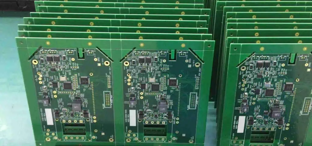
The border is the frame around the array that carries the tooling holes, the fiducials and the process coupon. A border that is too narrow distorts during handling and causes registration problems, and one that is too wide wastes material, so the width is a balance that most shops define as a rule. A border that varies from job to job makes the tooling unpredictable and forces a fresh setup for every product.
Fiducials belong in the border and in the array, and they should be positioned so that the assembly machine can see at least two of them in any position. Our tooling guide explains how the holes and the fiducials are placed relative to the array. Tooling holes should be round and generous, because a tight hole that is worn by repeated use loses the registration accuracy the whole flow depends on.
Breakaway Tabs and Depaneling
The tabs that connect each board to the frame have to be strong enough to survive the whole process and weak enough to break cleanly at the end of it. A tab that is too small breaks during handling, and one that is too large leaves a rough edge or damages the laminate when it is cut. Router bits, laser cutting and hand snapping all need a different tab geometry, so the depaneling method has to be chosen before the tabs are drawn.
Tab placement is a design decision with process consequences. Tabs near a fine pitch component, or near a connector that will be inserted later, transmit the depaneling stress into the wrong place. Our depaneling guide compares the methods and the stress each one puts into the board. Keeping the tabs on the long edges, away from connectors, is a simple rule that removes a large share of the mechanical complaints.
Registration and Layer Alignment
A panel with a high layer count and a dense array concentrates the registration challenge, because every layer has to move together through the press and the drill. Material movement during lamination is proportional to panel size, so a larger panel gives more absolute movement for the same percentage shrink. The scaling factor applied to the artwork should therefore be recorded per panel format and per material type, and reviewed whenever either of them changes.
The compensation applied to the artwork has to match the panel format and the material. A shop that changes panel size without revisiting the scaling factor will find that the inner layers no longer line up at the outer layer. Our outline guide covers how the finished dimensions are controlled. A shop that records the shrink for each combination builds a library that makes the next job with the same stack far more predictable.
Warpage and Thickness Effects
Warpage is worse on large panels and on asymmetric stack ups, because the imbalance in the copper and the resin has more leverage over a longer span. A bowed panel does not sit flat on a vacuum table and is difficult to print, place and reflow accurately. A symmetrical stack up and balanced copper on both sides of the core are the standard defences, and they matter more as the panel grows.
Thickness variation follows the same logic. A press that is flat and even over a small panel can show a measurable gradient over a large one, which changes the dielectric thickness and the impedance of the finished layer. If the gradient is significant, the panel may have to be reduced in size or the press cycle adjusted to even out the temperature across the book.
Process Control Points
Panel size should be agreed between the designer and the fabricator at the quotation stage rather than fixed by the design file alone. The agreement should record the format, the border width, the tab geometry, the tooling positions and the coupon location. That record then becomes the reference for every subsequent order of the same product, which removes a recurring argument.
Once production starts, the panel dimensions are checked against the tooling drawing and the array is inspected for tab damage before depaneling. Our production flow guide places these checks in the wider sequence from material release to final packing. Panel design is cheap to change at the start and expensive to change once tooling has been made, so the decision deserves attention early.
FAQ
Who decides the panel size? The fabricator and the assembly house decide it together, because the format has to suit both sets of equipment. The designer should be consulted about anything that affects the array layout.
Does a larger panel reduce cost? Usually, because more boards fit on a sheet and machine time is used more efficiently. The gain disappears if the larger panel warps, registers poorly or cannot run on the assembly conveyor.
How wide should the border be? Wide enough to carry the tooling holes, the fiducials and the coupon without distorting. Most fabricators publish a minimum, and going below it causes registration problems in the press and the drill.