PCB Assembly (PCBA): Process, Types, Testing, Standards & Manufacturing Guide
PCB assembly (PCBA) is the process of mounting and soldering electronic components onto a printed circuit board (PCB) to create a functional electronic assembly. A bare PCB provides the conductive pathways, pads, vias, and mechanical foundation needed to interconnect circuits, but it does not normally perform the intended electronic function until components are installed and electrically connected.
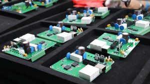
From smartphones and medical equipment to automotive electronics, industrial automation, telecommunications, and consumer devices, reliable PCB assembly is fundamental to modern electronics manufacturing.
For engineers, product designers, electronics manufacturers, and businesses developing new products, understanding what PCBA means is essential for selecting the right manufacturing process, controlling production costs, improving product reliability, and reducing time to market.
This guide explains what PCB assembly is, how PCB and PCBA differ, the major types of PCB assembly, the complete assembly process, inspection and testing methods, applicable IPC standards, and how to choose the right PCB assembly service provider.
What Is PCB Assembly?
PCB assembly (PCBA) is the manufacturing process of installing electronic components onto a fabricated PCB and establishing the required electrical and mechanical connections.
During the assembly process, components such as resistors, capacitors, inductors, diodes, transistors, integrated circuits, connectors, switches, sensors, and microcontrollers are placed onto designated PCB locations and soldered according to the assembly design.
Depending on the product architecture, components can be installed using surface mount technology (SMT), through-hole technology (THT), or a combination of both.
A typical PCBA workflow may include:
- PCB and design data verification
- Component and BOM verification
- Solder paste printing
- SMT component placement
- Reflow soldering
- THT component insertion
- Wave or selective soldering
- Cleaning when required
- AOI and other inspections
- Electrical and functional testing
- Final inspection and packaging
The exact process varies according to the PCB design, component mix, assembly volume, product requirements, and applicable industry standards.
How Does PCB Assembly Work?
After the bare PCB has been manufactured, it enters the assembly stage. The manufacturing team first verifies the PCB, bill of materials (BOM), assembly drawings, component specifications, and manufacturing data.
For SMT production, solder paste is deposited onto designated pads through a stencil. A pick-and-place machine then positions components onto the solder paste. The populated PCB passes through a reflow oven, where a controlled thermal profile melts and solidifies the solder, creating the required electrical and mechanical connections.
THT components are installed through plated or non-plated holes as specified by the design. Depending on the component arrangement and production requirements, they may be soldered using wave soldering, selective soldering, or manual soldering.
After soldering, the completed assembly undergoes inspection and testing before being released for final product integration.
Key Components Used in PCB Assembly
A PCBA may contain many different types of electronic components.
Passive components include:
- Resistors
- Capacitors
- Inductors
- Transformers
- Filters
These components control or condition electrical signals and power within the circuit.
Active components include:
- Transistors
- Diodes
- Microcontrollers
- Microprocessors
- Integrated circuits
- Power semiconductor devices
These components can control, process, amplify, switch, or otherwise manipulate electrical signals.
Other components may include:
- Connectors
- Switches
- Relays
- Sensors
- LEDs
- Crystals and oscillators
- Antenna components
- Power modules
The specific component mix depends on the functionality and architecture of the final electronic product.
PCB vs. PCBA: What Is the Difference?
PCB and PCBA are closely related terms, but they describe different stages and physical states of an electronic product.
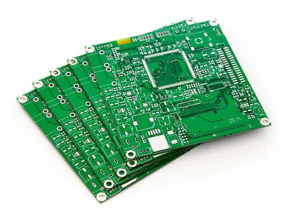
A PCB is the fabricated circuit board itself. A PCBA is the PCB after electronic components have been mounted and electrically connected.
| Feature | PCB | PCBA |
|---|---|---|
| Definition | Fabricated printed circuit board | PCB with electronic components installed |
| Components | Normally no components installed | Components mounted and soldered |
| Main purpose | Provides electrical interconnection and mechanical support | Performs the intended electronic functions |
| Manufacturing stage | PCB fabrication | PCB assembly |
| Typical processes | Imaging, etching, lamination, drilling, plating, solder mask, surface finish | Printing, component placement, soldering, inspection, testing |
| Testing | Dimensional, visual, electrical and other PCB-level tests | AOI, X-ray, ICT, FCT and other assembly-level tests |
| Final status | Ready for component assembly | Ready for product integration or further system assembly |
Why the Difference Matters
Understanding the difference between PCB and PCBA is important when requesting quotations and defining manufacturing requirements.
A PCB supplier may provide only the bare board, while a PCB assembly manufacturer may provide component sourcing, SMT/THT assembly, inspection, testing, programming, and other services.
PCB fabrication and assembly also require different equipment, materials, engineering controls, and quality processes.
For a complete electronics manufacturing project, the customer may purchase:
- Bare PCBs only
- PCB assembly only
- PCB and assembly separately
- A turnkey PCB assembly solution
The appropriate model depends on the customer’s supply chain and production requirements.
Why Is PCB Assembly Important?
PCB assembly is one of the most critical stages in electronics manufacturing because it directly affects the functionality, reliability, manufacturability, and service life of the final product.
Even a perfectly fabricated PCB can fail if components are incorrectly positioned, solder joints are defective, components are damaged, or the assembly process is poorly controlled.
Ensures Reliable Electrical Connections
Accurate component placement and properly formed solder joints establish the electrical connections required by the circuit. A controlled assembly process helps reduce defects such as opens, solder bridges, insufficient solder, component misalignment, and polarity errors.
Improves Product Reliability
Reliable solder joints and properly installed components help electronic assemblies withstand their intended operating conditions, including temperature cycling, vibration, humidity, and mechanical stress when applicable.
Supports High-Volume Manufacturing
Automated SMT assembly allows manufacturers to place large numbers of components rapidly and consistently. Automated equipment improves repeatability and makes high-volume production more efficient.
Reduces Rework and Lifecycle Costs
Better process control can reduce manufacturing defects, rework, field failures, warranty claims, and maintenance costs. Preventing defects during production is generally more efficient than correcting them after products have entered the market.
Enables Compact and High-Density Electronics
Modern SMT components allow designers to place many functions into relatively small PCB areas. This is particularly important for smartphones, wearable devices, communication equipment, medical electronics, and other space-constrained products.
Types of PCB Assembly
Different electronic products require different assembly methods. PCB size, component type, board complexity, production volume, reliability requirements, and product architecture all influence the appropriate PCB assembly method.
1. Surface Mount Technology (SMT)
Surface mount technology (SMT) is one of the most widely used PCB assembly methods in modern electronics manufacturing.
SMT components are mounted directly onto PCB surface pads rather than requiring their leads to pass through the board.
Major advantages include:
- High component density
- Compact product design
- High-speed automated assembly
- Excellent repeatability
- Compatibility with small components
- Efficient high-volume production
SMT is widely used in consumer electronics, telecommunications, computing equipment, automotive electronics, medical devices, and industrial systems.
2. Through-Hole Technology (THT)
Through-hole technology (THT) involves inserting component leads through holes in the PCB and soldering them to corresponding pads.
THT can provide strong mechanical anchoring and is often used for components that experience significant mechanical or thermal stress, such as:
- Large connectors
- Transformers
- Relays
- Switches
- Certain power components
- Large capacitors
However, THT generally requires more PCB area than SMT and may involve additional assembly operations.
3. Mixed Technology Assembly
Many modern products use both SMT and THT components on the same PCB.
This mixed technology PCB assembly combines the compactness and automation advantages of SMT with the mechanical benefits of selected THT components.
Mixed assembly is common when a PCB contains small ICs and passive components together with large connectors, switches, transformers, or mechanically stressed components.
4. Single-Sided PCB Assembly
In single-sided assembly, components are primarily installed on one side of the PCB.
This approach can simplify the manufacturing process and may be cost-effective for relatively simple circuit designs with lower component density.
5. Double-Sided PCB Assembly
Double-sided PCB assembly places components on both sides of the circuit board.
This approach allows designers to use the available board area more efficiently without necessarily increasing the overall PCB footprint.
However, double-sided assembly requires careful consideration of component height, thermal profiles, assembly sequence, board support, and soldering processes.
6. Multilayer PCB Assembly
Multilayer PCB assembly is used for complex electronic products requiring high routing density, controlled power distribution, high-speed signaling, or compact system integration.
Multilayer PCBAs are widely used in:
- Telecommunications equipment
- Servers and computing systems
- Medical electronics
- Aerospace and defense electronics
- Automotive systems
- Industrial control equipment
- High-performance electronic devices
High layer count alone does not guarantee better performance. The PCB stackup, grounding strategy, power distribution, impedance control, component placement, and signal integrity design must all work together.
PCB Assembly Process
The PCB assembly process consists of multiple controlled manufacturing stages. Each stage contributes to the final electrical and mechanical reliability of the PCBA.
1. PCB Design and Manufacturing Data Verification
Before assembly begins, the manufacturer reviews available production data, which may include:
- Gerber files
- Drill files
- BOM
- Pick-and-place files
- Assembly drawings
- Component specifications
- PCB fabrication specifications
Design-for-manufacturing (DFM) and design-for-assembly (DFA) reviews can help identify potential production problems before components are mounted.
2. BOM and Component Verification
The bill of materials is checked against the assembly data.
Important considerations include:
- Part number
- Manufacturer information
- Package type
- Component value
- Tolerance
- Polarity
- Lifecycle status
- Approved alternatives
- Quantity requirements
Reliable component sourcing is particularly important for production continuity and counterfeit-risk reduction.
3. Solder Paste Printing
For SMT assembly, solder paste is applied to designated PCB pads using a stencil.
Printing quality depends on factors such as:
- Stencil design
- Aperture dimensions
- Solder paste properties
- PCB surface condition
- Printing pressure
- Squeegee speed
- Paste storage and handling
- Environmental conditions
Poor solder paste deposition can lead to insufficient solder, solder bridges, component shifting, and other defects.
4. SMT Component Placement
A pick-and-place machine accurately positions SMT components onto the PCB.
Modern placement equipment can handle a wide range of component packages, from small passive components to complex IC packages.
Correct placement depends on:
- Component coordinates
- Rotation
- Polarity
- Package recognition
- Feeder setup
- PCB fiducials
- Placement accuracy
5. Reflow Soldering
The populated PCB passes through a reflow oven using a controlled temperature profile.
The profile normally includes stages such as:
- Preheating
- Thermal soaking
- Reflow
- Controlled cooling
The exact profile depends on the solder alloy, PCB design, component requirements, thermal mass, and manufacturer’s process specifications.
The goal is to create reliable solder joints without exceeding component or PCB thermal limitations.
6. Through-Hole Component Insertion
THT components are inserted into their designated holes either manually or using automated equipment where appropriate.
Component orientation and lead positioning must be carefully controlled to prevent assembly errors.
7. Wave or Selective Soldering
Wave soldering can efficiently solder suitable THT assemblies, particularly in higher-volume production.
Selective soldering is useful when only specific through-hole areas require soldering, especially when SMT components are already populated on the same board and must be protected from unnecessary thermal exposure.
Manual soldering may also be used for prototypes, low-volume production, rework, or specific components that are not suitable for automated soldering.
8. PCB Cleaning
Not every PCBA requires the same cleaning process.
If the selected soldering materials and product requirements permit a no-clean process, additional cleaning may not be necessary. However, some assemblies require post-solder cleaning to remove flux residues or other contaminants.
Cleaning requirements are especially important for products involving:
- High impedance circuits
- Sensitive sensors
- High-voltage applications
- Fine-pitch components
- Conformal coating
- Long-term environmental exposure
The cleaning method should be compatible with the PCB materials, components, soldering materials, and product requirements.
9. In-Process Inspection
Inspection points throughout the production line help identify defects before they move to subsequent manufacturing stages.
Early defect detection can reduce:
- Rework
- Scrap
- Production delays
- Yield loss
- Final inspection failures
Process monitoring may include solder paste inspection, placement verification, AOI, X-ray inspection, and other controls depending on the product.
10. Electrical and Functional Testing
After assembly, the PCBA may undergo electrical and functional testing.
Testing requirements vary significantly depending on the product. Possible methods include:
- Continuity and isolation testing
- ICT
- FCT
- Boundary-scan testing
- Programming and firmware verification
- Communication interface testing
- Power-up testing
The selected test strategy should be defined according to the product’s electrical architecture and quality requirements.
PCB Assembly Inspection and Testing
A comprehensive PCB assembly testing strategy helps identify manufacturing defects before the finished PCBA reaches the customer or final product.
Automated Optical Inspection (AOI)
AOI uses cameras and image-processing algorithms to inspect the assembled PCB.
It can detect many visible assembly defects, including:
- Missing components
- Incorrect component placement
- Component polarity errors
- Solder bridges
- Insufficient solder
- Misalignment
- Certain solder-joint defects
AOI is particularly valuable for high-volume SMT production because inspection can be performed rapidly and consistently.
X-Ray Inspection
X-ray inspection provides visibility into solder joints and structures that cannot be adequately inspected from the surface.
It is particularly useful for packages and connections such as:
- BGA
- QFN
- Bottom-terminated components
- Hidden solder joints
- Certain complex THT structures
X-ray inspection is non-destructive and can reveal certain internal soldering defects that optical inspection cannot see.
In-Circuit Test (ICT)
In-circuit testing (ICT) uses dedicated test fixtures and electrical measurements to evaluate components and circuit connections.
Depending on the test strategy, ICT can identify:
- Open circuits
- Short circuits
- Incorrect component values
- Missing components
- Certain component faults
- Incorrect electrical connections
ICT requires appropriate test access and fixture development, so its cost and suitability depend on production volume and PCB design.
Functional Circuit Test (FCT)
Functional testing (FCT) evaluates whether the completed PCBA performs its intended electrical functions.
The board may be powered and operated under controlled test conditions while its interfaces, outputs, communication functions, sensors, or other system functions are verified.
FCT is especially useful when simply checking individual components cannot confirm whether the complete assembly operates correctly.
Factors Affecting PCB Assembly Quality
High-quality PCBA manufacturing depends on much more than soldering equipment. Materials, component quality, PCB design, process control, equipment calibration, inspection, and engineering expertise all influence the final result.
Component Quality
Components should come from reliable supply channels and meet the specified electrical, mechanical, and environmental requirements.
Poor-quality, obsolete, damaged, or counterfeit components can cause failures even when the assembly process itself is properly controlled.
Solder Paste Quality
Solder paste composition, particle characteristics, storage conditions, handling, stencil design, and printing parameters all influence soldering performance.
Improperly handled solder paste can contribute to defects such as solder bridges, insufficient solder, poor wetting, and inconsistent solder joints.
Process Control
Stable manufacturing parameters are essential for repeatable assembly.
Important process variables may include:
- Solder paste printing parameters
- Placement accuracy
- Reflow temperature profile
- Conveyor speed
- Soldering conditions
- Cleaning parameters
- Inspection settings
Process control should be supported by documented procedures and appropriate monitoring.
PCB Design for Assembly
PCB layout has a major impact on assembly efficiency and quality.
Good PCB design for assembly (DFA) considers:
- Component spacing
- Pad geometry
- Component orientation
- Fiducial placement
- Thermal considerations
- Assembly accessibility
- Solder mask design
- Test-point accessibility
Designing for manufacturability before production begins can reduce unnecessary rework and improve production yield.
Operator and Engineering Expertise
Although modern PCB assembly lines are highly automated, skilled engineers and technicians remain important.
They are responsible for:
- Equipment programming
- Process optimization
- Troubleshooting
- Quality analysis
- Rework
- Production validation
- Continuous improvement
Automation and human expertise work together to maintain consistent manufacturing results.
Inspection and Quality Control
A robust quality system may include:
- Incoming material inspection
- Solder paste inspection
- AOI
- X-ray inspection
- In-process inspection
- ICT
- FCT
- Final visual inspection
- Traceability records
The exact combination depends on product complexity, industry requirements, production volume, and customer specifications.
PCB Assembly Applications
PCB assembly services support virtually every modern electronics sector.
Consumer Electronics
Consumer products such as:
- Smartphones
- Tablets
- Laptops
- Smart TVs
- Game consoles
- Wearable devices
- Home appliances
rely heavily on compact, high-density PCB assemblies.
Automotive Electronics
Modern vehicles contain numerous electronic control systems for:
- Powertrain control
- Body electronics
- Infotainment
- Navigation
- Driver assistance
- Lighting
- Battery management
- Charging systems
Automotive PCBAs may need to withstand vibration, temperature variation, humidity, and other environmental conditions according to their intended application.
Medical Electronics
Medical equipment can require highly controlled PCB assembly processes because electronic performance and reliability can directly affect device functionality.
Applications include:
- Patient monitoring equipment
- Diagnostic equipment
- Imaging systems
- Laboratory instruments
- Portable medical devices
The required quality system and regulatory considerations depend on the specific medical device and market.
Industrial Automation
Industrial PCBAs are used in:
- PLC systems
- Motor controllers
- Robotics
- Industrial sensors
- Control systems
- Power electronics
- Monitoring equipment
These assemblies may be designed for continuous operation in demanding industrial environments.
Telecommunications
High-density PCBAs form the foundation of many communication systems, including:
- Network switches
- Routers
- Wireless communication equipment
- Optical communication systems
- Data infrastructure
High-speed applications require careful attention to PCB stackup, impedance control, signal integrity, power integrity, and assembly quality.
IPC Standards for PCB Assembly
Industry standards provide a common framework for PCB manufacturing, assembly, soldering, inspection, and acceptance.
Several IPC standards are particularly relevant to PCB assembly.
IPC-A-610: Acceptability of Electronic Assemblies
IPC-A-610 defines visual acceptability criteria for electronic assemblies.
It covers areas such as:
- Component mounting
- Soldering
- Lead and terminal conditions
- Mechanical assembly characteristics
- Various visible workmanship conditions
It is widely used as a reference for evaluating assembled electronic products.
J-STD-001: Requirements for Soldered Electrical and Electronic Assemblies
IPC J-STD-001 establishes requirements and guidance for soldered electrical and electronic assemblies.
It addresses materials, soldering processes, workmanship, and related requirements needed to produce reliable soldered connections.
IPC-2221: Generic Standard on Printed Board Design
IPC-2221 provides generic design guidance for printed boards.
Although it is primarily a PCB design standard rather than an assembly acceptance standard, its design principles can influence manufacturability, reliability, spacing, thermal management, and assembly requirements.
Other IPC standards may also apply depending on the PCB type, product category, material system, and customer requirements.
How to Choose the Right PCB Assembly Manufacturer
Choosing the right PCB assembly manufacturer can directly affect product quality, production cost, delivery performance, and long-term reliability.
Before selecting a supplier, consider the following factors.
Manufacturing Experience
Look for a manufacturer with experience handling PCB designs similar to your application.
Relevant experience may include:
- SMT assembly
- THT assembly
- Mixed technology assembly
- High-density PCB assembly
- Fine-pitch components
- Prototype production
- Low-volume production
- High-volume production
Inspection and Testing Capability
A capable manufacturer should have an inspection and testing strategy appropriate for the product.
Potential capabilities include:
- SPI
- AOI
- X-ray
- ICT
- FCT
- Electrical testing
- Programming
- Functional verification
Not every project requires every test method, so the manufacturer should be able to recommend an appropriate approach based on the product design.
Component Sourcing and Supply Chain Management
Reliable component procurement is critical to production continuity.
A strong supply chain process can help reduce risks associated with:
- Counterfeit components
- Component shortages
- Obsolete parts
- Unexpected substitutions
- Production delays
Customers should clearly define whether the assembly provider is responsible for complete component procurement or whether components will be supplied by the customer.
Engineering and DFM Support
Engineering support can identify manufacturing problems before production starts.
A capable PCB assembly service provider may review:
- PCB layout
- BOM
- Component footprints
- Assembly drawings
- Component availability
- Test-point accessibility
- Manufacturing constraints
Early DFM and DFA feedback can prevent costly redesigns later in the production cycle.
Production Flexibility
The ideal supplier should be able to support the project’s production stage, whether it is:
- Prototype assembly
- Engineering validation
- Small-batch production
- Medium-volume production
- Mass production
A scalable manufacturing process makes it easier to move from prototype to commercial production.
Cost and Overall Value
Price is important, but it should not be the only selection criterion.
The lowest quotation may not represent the lowest total cost if it leads to:
- Higher defect rates
- More rework
- Component shortages
- Production delays
- Inadequate testing
- Field failures
A better evaluation considers total manufacturing value, including quality, engineering support, supply chain reliability, testing, production capacity, and delivery performance.
PCB Assembly Services from Kingda
Kingda can support customers with PCB assembly and related electronics manufacturing requirements based on the specific PCB design, component configuration, production volume, and testing requirements.
Depending on the project, customers can evaluate requirements such as SMT assembly, THT assembly, mixed technology assembly, PCB sourcing, component procurement, inspection, electrical testing, and functional verification.
When selecting an assembly partner, it is important to provide complete and accurate manufacturing data, including the BOM, Gerber files, pick-and-place data, assembly drawings, PCB specifications, component requirements, and testing requirements where applicable.
This allows the manufacturer to evaluate the project accurately and establish an appropriate production process.
Conclusion
PCB assembly (PCBA) transforms a fabricated circuit board into a functional electronic assembly by accurately installing and electrically connecting electronic components. The process involves much more than simply soldering components. It combines PCB design verification, material control, SMT and THT placement, soldering, inspection, testing, and quality management.
Understanding the difference between PCB and PCBA helps companies select the correct manufacturing service and avoid inaccurate quotations or incomplete production requirements. Choosing between SMT, THT, mixed technology, single-sided, double-sided, and multilayer assembly depends on the product’s electrical, mechanical, environmental, and production requirements.
Reliable PCB assembly manufacturing also requires appropriate inspection and testing. AOI, X-ray, ICT, FCT, and other testing methods can be combined according to the design and risk profile of the product.
As electronic products become smaller, more powerful, and more complex, selecting an experienced PCB assembly manufacturer becomes increasingly important. A capable manufacturing partner can help improve manufacturability, maintain process consistency, reduce production risks, and support the transition from prototype development to volume production.
For companies developing new electronic products, the right PCBA strategy can ultimately improve product reliability, production efficiency, and time to market.