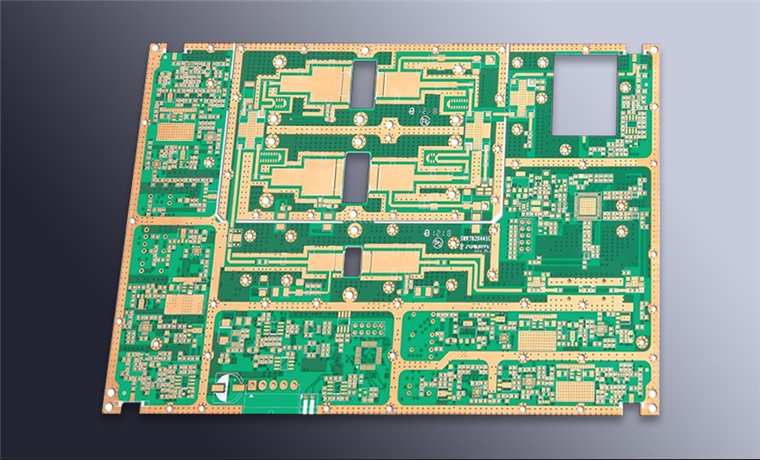
Backdrilling To Remove Via Stubs
A plated through hole connects the layers it passes through, but it also continues past the last layer it serves and ends at the far side of the board. That unused length is the via stub, and at high frequency it behaves as an open circuited transmission line branch that reflects energy back into the signal.
This article explains why the stub matters, how backdrilling removes it, how the remaining depth is controlled, and what the process costs.
Why The Stub Matters
The stub is a length of copper that is connected to the signal at one end and open at the other. Energy travelling along the signal divides at the junction, and the part that enters the stub travels to its end, reflects, and returns after a delay set by the stub length. If the round trip delay matches the period of a component in the signal, the reflected energy adds in phase and the stub resonates, which produces a sharp notch in the insertion loss and a peak in the return loss at a specific frequency.
The frequency of that resonance falls as the stub gets longer. A stub of a few millimetres places the first resonance well above the useful band of most designs, while a stub that spans the full thickness of a thick backplane places it squarely inside the band. This is why the problem appears on thick boards with connectors mounted on the far side and not on thin boards with shallow layers: the stub length is a geometric consequence of the stack and the connector placement. The line behaviour that the stub disturbs is described under PCB routing with microstrip and stripline.
How Backdrilling Works
Backdrilling removes the stub by re-entering the finished hole from the side where the stub ends and cutting it away with a drill of slightly larger diameter than the original hole. The larger diameter is what allows the cutter to remove the plating without damaging the walls of the remaining hole. The cut is made to a controlled depth, measured from the board surface, and the target is to leave the shortest stub the process can hold without cutting into the layer that the via serves.
The process is done after plating and before the outer layer finish, and it can be done before or after the outer layers are patterned. The depth is set from the stackup, with the tolerance of the press, the copper thickness and the drill depth all contributing. A cut that is too shallow leaves the stub that the process was meant to remove; a cut that is too deep removes part of the pad or the barrel of the layer above, which is a scrap. The stub that remains is called the residual stub, and it is quoted as a number on the fabrication drawing. The wider consequences for high speed construction are described under the advantages of multilayer construction at high speed.

Controlling The Residual Stub
Three variables decide the residual stub: the accuracy of the drill depth, the thickness tolerance of the laminate between the target layer and the surface, and the definition of the target. The laminate thickness is the largest term, because a press cycle produces a board whose thickness varies across the panel and between panels. For this reason the depth is set from a measurement of the actual panel rather than from a nominal stackup, and a common practice is to drill a test hole and measure it before the production holes are cut.
Electrical test of the result is done on a coupon carrying a chain of backdrilled vias, measured for insertion loss and for the resonance that the stub would produce. A stub that is longer than intended shifts the resonance down in frequency, and the position of that notch is a direct measurement of the residual stub length. Where the design is sensitive, the coupon is measured per panel lot rather than per qualification, because the laminate thickness varies from lot to lot.
Design Rules For Backdrilled Vias
A backdrilled via needs a larger clearance around the hole than a normal one, because the cutter is larger than the original drill and it has to reach the surface without touching an adjacent feature. The antipad on the layers the stub passes through must also be large enough to withstand the cutting. Both requirements reduce the routing space around the via, and they are normally applied to the whole via field rather than only to the vias that will be cut, so that the design remains manufacturable if the decision changes.
The via also needs to be identified clearly in the drill data, because the cutter has to be the right size and the depth has to be correct for each via. A common approach is a separate drill table for the backdrilled holes, with a depth measured from the opposite side. Mixing backdrilled and normal vias of the same diameter in one table is a reliable way to produce a panel where some holes are cut too deep. The routing that brings the signals to those vias is treated under routing high frequency traces and data buses.
Cost And Where It Is Justified
Backdrilling adds a process step, a drill programme and a test coupon, and it reduces the number of vias that a panel can carry because of the extra clearance. It is justified when the signal band of the product overlaps the resonance that an uncut stub would produce. That is normally the case for a high speed serial link running through a thick backplane, and it is normally not the case for a low speed control board on a thin stack.
The signal integrity decision should be made from a calculation rather than from a habit of backdrilling everything. Estimating the stub length from the stackup, and comparing the resulting resonance with the highest frequency of interest, takes minutes and decides the question. Where the result is marginal, the cheaper alternative is usually to change the layer that the signal uses, so that the via serves a layer closer to the far side and the stub becomes short without any drilling at all. That trade, between layer assignment and process cost, is part of how layout decisions affect production.
Inspection And Common Faults
The inspection of a backdrilled hole is by section, which shows the remaining stub and the condition of the cut. A good cut leaves a clean shoulder where the plating was removed and a stub of the intended length; a poor one leaves a ragged edge, plating burrs inside the remaining hole or a stub that is visibly longer on one side than the other because the hole was not perpendicular to the board.
The other fault to look for is damage to the layer above. A cutter that is slightly too deep or a panel that is thinner than measured will cut into the barrel of a layer that is still in use, and the damage appears as a thinned or broken barrel on that layer. It is detected by a resistance chain or by section, and it is the reason that the depth margin is set by the thickness tolerance of the panel and not by the nominal target alone.
FAQ
Does backdrilling always improve the signal? It removes a resonance, which is an improvement where the resonance is inside the band of interest. Where the band is far below the resonance, the drilling changes nothing electrically and only adds cost.
Can a stub be reduced without backdrilling? Yes, by routing the signal on a layer closer to the far side of the board, which shortens the stub geometrically. That approach is limited by the routing capacity of the layers available.
How is the residual stub verified? By a coupon that carries a chain of backdrilled vias, measured for the frequency of the stub resonance, and by sections taken from the panel to confirm the cut depth and the quality of the shoulder.