Backdrilling: Preparation, Placement and Process Control
Backdrilling is the controlled removal of the unused portion of a plated through hole. A via that runs the full thickness of a thick board leaves a stub below the layer where the signal joins, and at high frequency that stub behaves as a resonant transmission line, producing a notch in the channel response. Removing it improves the signal, and the operation has to be done without damaging the barrel that remains.
What the Stub Does
A plated through hole that carries a signal from an inner layer to the surface also continues to the bottom of the board. The section of the barrel that extends past the connection point is the stub.
At low frequency the stub is invisible. As the frequency rises, the stub starts to behave as a section of transmission line with an open end, and the reflection from the end returns to the signal path. The result is a resonance that appears as a dip in the insertion loss at a frequency set by the stub length.
Because the effect depends on length, it is worst on a thick board. A stub of a few millimetres on a backplane produces a notch inside the band of a modern serial link, which is the reason backdrilling is specified on that class of product and not on a thin board.
How Much to Remove
The depth is set so that a short residual stub remains rather than removing the barrel to the connection point. The residual is a compromise: it is short enough that its resonance is above the band of interest and long enough that the drilling has margin.
The residual is usually specified as a length, for example a fraction of a millimetre, or as a fraction of the dielectric thickness. The specification should be a dimension with a tolerance rather than a description.
The depth has to be measured from the surface of the finished board, which means the plating and the finish thickness are part of the tolerance. A depth set from the laminate surface will be wrong by the thickness of the copper that was added afterwards.
Depth Control and the Machine
Backdrilling is done with a drill whose diameter is slightly larger than the finished hole, so that the plating is removed without touching the barrel that remains. The diameter has to be chosen from the plating thickness and the hole tolerance.
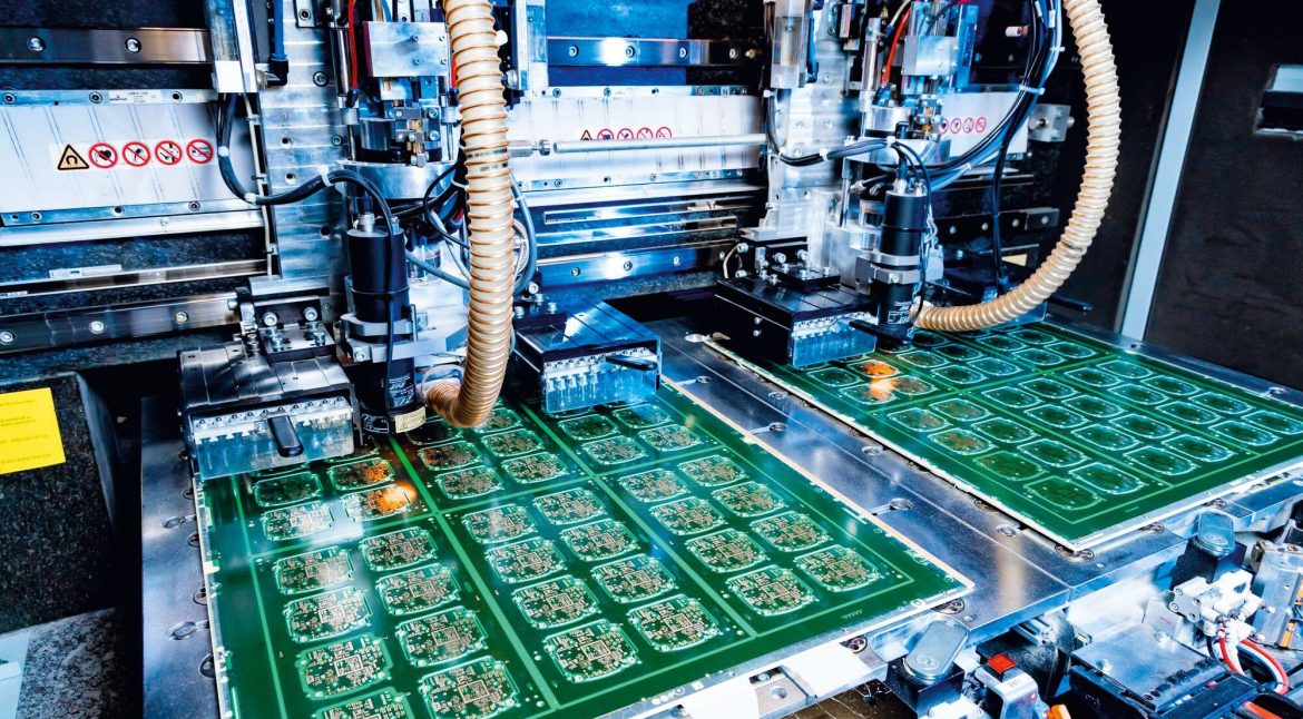
The depth is controlled by the machine rather than by the drill. A machine with a depth control based on the panel surface, combined with a measurement of the panel thickness at each position, holds the tolerance better than one that uses a single reference for the whole panel.
The drilling parameters are gentler than for a standard hole. A high feed rate produces a rough wall and can pull the plating, and the tool wear is faster because the drill is removing plating as well as laminate.
Damage Mechanisms
The drilling generates heat and debris inside the hole. Debris that is not removed is a conductive path between layers, and the cleaning after backdrilling has to be verified rather than assumed.
The plating at the connection point can be damaged if the depth control overshoots. The damage may be a partial crack that passes the electrical test when cold and fails at temperature, which is why the depth tolerance is a reliability parameter and not only an electrical one.
The barrel above the remaining stub sees a change in its mechanical support. A barrel that has been shortened is stiffer at the top and the transition to the laminate is a stress concentration, so the design should keep the connection point away from the surface where the geometry allows it.
Process Sequence
Backdrilling is normally done after the plating and the imaging, before the surface finish and the final drilling of the mechanical holes. The order matters because the backdrilled hole has to be cleaned before the finish is applied.
The panel is held in a fixture that references the same datum as the drilling that made the original holes. A different datum introduces a registration error that changes the depth and the concentricity of the backdrill.
The debris is removed by a combination of vacuum, air and a chemical cleaning step. The cleaning should be verified on a sample by a section and by an ionic cleanliness test, because a conductive path inside a backdrilled hole is difficult to find later.
Design Rules
The stubs that matter are the ones on the highest speed nets. Backdrilling every via on a panel costs money and adds risk, so the specification should list the nets or the layers that require it.
The via should be placed so that the backdrill has access from the opposite side, which means avoiding a component or a connector directly above the hole. A via that cannot be reached from the other side has to be left with its stub.
The pad and the anti pad dimensions have to allow for the larger backdrill diameter. A backdrill that encroaches on a neighbouring net or on a plane creates a short or a clearance violation that is not visible on the outer layers.
Verification
A cross section is the definitive check. It shows the residual stub, the condition of the plating at the connection point and the presence of debris, and the measurement can be compared with the specification directly.
The electrical verification is the channel measurement. A comparison of the insertion loss before and after backdrilling shows the removal of the notch, and the result is the reason the process is specified.
The stub length should be measured on samples through the production run, because the depth control drifts with the tool wear and with the panel thickness variation. A single measurement at the start of a run does not describe the end of it.
Cost and Where It Is Applied
Backdrilling adds a process step, a cleaning step and a risk of damage, so it is applied to the nets that need it rather than to the whole panel. On a backplane the list is usually the serial links and the clock, and the remaining nets are left alone.
The cost is per hole rather than per panel, so a design that concentrates the high speed routing on one area of the board pays less than one that spreads it across the whole panel. That is a layout decision as much as a process one.
The benefit is a wider eye at the receiver, which is what the signal integrity budget is measured by. Where the channel already has margin, the process removes cost from the product without adding value, and where the margin is thin it is often the cheapest available remedy.
Practical Rules
Specify the residual stub as a dimension, reference the depth to the finished board and list the nets that need the process. Verify the depth by section and the response by measurement.
Record the depth and the cleaning data with the build records and the dimensional stability data, and review the aspect ratio data and the high speed design rules when a thick board is designed.
FAQ
What is a via stub? The unused part of a plated through hole below the layer where the signal joins. At high frequency it behaves as an open transmission line and creates a resonance.
Why leave a residual stub? Removing the barrel to the connection point risks damaging the plating. A short residual keeps the resonance above the band of interest while leaving the joint intact.
How is backdrilling verified? By a cross section that measures the residual stub and shows the plating condition, supported by a channel measurement that shows the notch has been removed.