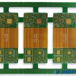
Fiducial Mark: Practical Checks for Production
A fiducial mark is a small copper feature that the placement machine uses to find the board. The machine photographs the marks, calculates their position, and offsets its program so that components land on the pads regardless of small errors in the position of the board on the conveyor.
Fiducial marks are cheap to add and expensive to omit. A board without them forces the operator to teach positions manually and leaves every board placed with whatever positional error the panel and the conveyor happened to introduce.
How Fiducials Are Used
The placement machine camera finds the fiducial by looking for a shape of high contrast against its background. Two or three marks are located, and the machine solves for the translation and rotation of the board relative to its program. The result is applied to every placement on that board.
The accuracy of the correction depends on the accuracy of the mark itself. A mark with a poorly defined edge, or one that is partly covered by solder mask, gives the machine a position that is a fraction of a millimetre away from the truth, and that error is then applied everywhere.
Size, Shape And Contrast
The usual fiducial is a filled circle of 1 mm diameter with a clear area of 2 mm around it. The copper is left free of solder mask and is protected by the same surface finish as the pads, so the contrast comes from the metal against the laminate.
Contrast is what the camera needs, so a dark finish on a dark laminate is a poor combination. A mark on a copper plane needs a mask opening larger than the mark, while a mark on bare laminate needs enough metal to give a clean silhouette. The finish choices involved are described under PCB design quality characteristics.
Global And Local Fiducials
Global fiducials are placed on the panel or board outline and used to align the whole assembly. Two are enough for translation and rotation, and three allow the machine to detect stretch as well, which is useful on a large thin board.

Local fiducials are placed close to a fine pitch component and used to correct the position of that component alone. They matter for a ball grid array or a fine pitch quad flat pack, where the accumulated error across a large board would otherwise exceed the placement tolerance. The placement sequence itself is described under placement order and pad positioning.
Clearance And Keepout
The keepout around a fiducial must be free of anything that could confuse the camera, including copper traces, vias, silkscreen and component bodies. The usual rule is a clear ring with a diameter of at least twice the mark diameter.
Clearance also has to survive assembly. A fiducial placed where a component will later be mounted is useless, and a mark inside a solder paste stencil opening will be covered with paste. The keepout should be checked against the placement and the stencil data, not only against the copper layers.
Placement On The Panel
Fiducials are placed on the panel as well as on each board, and the two are used for different purposes. Panel marks align the stencil printer and the panel in the machine, while board marks correct each individual circuit before placement.
A panel should carry at least three marks, placed asymmetrically so that the machine cannot confuse the orientation. On a small board, marks in two diagonal corners are common practice and are usually sufficient for reliable placement.
Common Errors
The most common error is a fiducial that is covered by solder mask, which removes the contrast the machine needs. The second is a mark with an insufficient clear area, where a nearby trace or the edge of a via is picked up as part of the shape.
The third is a design that places marks on only one board of a panel, so that the rest are placed without correction. Fiducials cost nothing in copper terms and should be present on every board that carries fine pitch parts. How these features are included in the fabrication data is described under PCB design and fabrication.
Process Control and Verification
On a design of this kind, panel is the item that decides how the rest of the board is arranged. A short note on the drawing about handling, storage or packaging is often worth more than an extra decimal place on a tolerance. Where a value sits close to a process limit, the drawing should say so, since the shop can then open the process window rather than working to a nominal figure that carries no tolerance.
A stack-up that is drawn rather than described removes most of the ambiguity from a quotation, and it lets the fabricator price the board against the dielectric and copper weights that will actually be used. Where the requirement is not written down, the shop supplies its own default, and the default is chosen for the process rather than for the design.
The measurements that matter are the repeatable ones: conductor width and spacing, annular ring, finished hole size, plating thickness and surface finish are all verifiable on a coupon that travels with the panel. Running a first article through the same checks as the production panel confirms that the two agree, and that comparison is the cheapest form of process control available at prototype stage.
Process Control and Verification
On a design of this kind, panel is the item that decides how the rest of the board is arranged. A short note on the drawing about handling, storage or packaging is often worth more than an extra decimal place on a tolerance. Where a value sits close to a process limit, the drawing should say so, since the shop can then open the process window rather than working to a nominal figure that carries no tolerance.
A stack-up that is drawn rather than described removes most of the ambiguity from a quotation, and it lets the fabricator price the board against the dielectric and copper weights that will actually be used.
Process Control and Verification
On a design of this kind, panel is the item that decides how the rest of the board is arranged. A short note on the drawing about handling, storage or packaging is often worth more than an extra decimal place on a tolerance. Where a value sits close to a process limit, the drawing should say so, since the shop can then open the process window rather than working to a nominal figure that carries no tolerance.
A first article check confirms that the process and the drawing agree on the points listed above, and that the coupon data supports the values used in the design.

Where a measurement falls outside the expected window, the sample is retained so that the cause can be established before the balance of the batch is released.
FAQ
How many fiducials does a board need? Three is the safe answer for a large board, allowing stretch to be detected. Two are adequate for a small, thick board where the machine has few other sources of error.
Can a pad or a via be used as a fiducial? Sometimes, but only if it has the same clean edge and clear area. A dedicated mark takes almost no space and avoids the uncertainty.
Do fiducials need to be on the bottom side? They are needed on the side being populated. A double sided assembly needs marks on both sides, and they do not have to be in the same place.