PCB Inner Layer Circuit Manufacturing Process
The inner layer circuit is the core structure of a multilayer circuit board, and its manufacturing quality directly determines the electrical performance, stability, and reliability of the final PCB product.
With electronic devices continuously developing toward miniaturization, higher performance, and increased integration, PCB inner layer circuits require increasingly higher levels of precision and manufacturing consistency.
A complete PCB Manufacturing Process involves multiple carefully controlled stages, and inner layer fabrication is one of the most critical steps. From material preparation and surface treatment to image transfer, etching, and drilling, every process parameter affects the accuracy and reliability of the finished circuit board.
For advanced products such as Multilayer PCB, high-frequency boards, and HDI PCB, precise inner layer circuit production is essential for achieving excellent electrical performance and long-term reliability.
Material Cutting: Establishing a Precise Foundation
Material cutting is the first step in PCB inner layer circuit manufacturing.
During this stage, production engineers cut copper-clad laminates into working panels according to the designed production dimensions and Gerber data. The dimensional accuracy of this process is extremely important because all subsequent manufacturing steps depend on the initial panel size.
If the cutting dimensions are inaccurate, problems such as inner layer circuit displacement and layer misalignment during multilayer lamination may occur.
Modern PCB manufacturers typically use high-precision CNC cutting equipment to ensure accurate dimensions and clean edges. The selection of cutting tools must also match the material type and thickness of the copper-clad laminate.
Proper edge finishing and corner rounding are also important. These treatments help improve production yield and prevent potential defects during later processes such as image transfer and lamination.
Professional PCB Manufacturing Services use advanced equipment and strict process control to maintain consistent inner layer production quality.
Surface Preparation: Copper Cleaning and Roughening
Surface preparation is a critical step that improves copper surface cleanliness and adhesion performance before dry film lamination.
Although this process may appear simple, it has a significant impact on the success of inner layer circuit fabrication.
Before applying dry film, the copper surface must be carefully cleaned and treated. Common surface treatment methods include:
Mechanical Brushing
Mechanical brushing is a traditional copper surface treatment method with relatively low cost and simple operation.
However, it is less suitable for thin boards and fine-line PCB applications because excessive brushing force may stretch the substrate or create deep scratches.
Deep brush marks can reduce dry film adhesion and may cause issues such as plating leakage or residual adhesive contamination.
Sand Blasting
Sand blasting provides a more uniform copper surface roughness compared with mechanical brushing.
It offers better dimensional stability and can be used for thin boards and fine-line circuit processing.
However, particles from blasting materials may remain on the board surface, and equipment maintenance requirements are relatively high.
Chemical Micro-Etching
Chemical treatment is widely used in advanced PCB production.
Through controlled chemical micro-etching, the copper surface can achieve a clean and uniform microscopic roughness, significantly improving dry film adhesion.
During production, parameters such as chemical concentration, temperature, and processing time must be precisely controlled to achieve optimal surface performance.
Dry Film Lamination: Ensuring Accurate Pattern Transfer
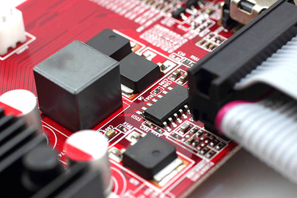
The lamination process applies photosensitive dry film tightly onto the treated copper surface.
This step directly affects the clarity and accuracy of circuit pattern transfer during exposure.
For thin boards and high-density circuit designs, controlling dry film wrinkles is essential. The film must be applied smoothly without bubbles or folds.
Key parameters include:
- Lamination temperature
- Lamination pressure
- Roller cleanliness
- Roller surface condition
Proper temperature and pressure allow the adhesive layer inside the dry film to soften and bond effectively with the copper surface.
Any contamination or uneven roller pressure may result in poor adhesion and negatively affect the following exposure process.
Exposure: Creating High-Precision Circuit Patterns
Exposure is one of the most important stages in PCB inner layer circuit manufacturing.
Modern PCB production commonly uses LDI (Laser Direct Imaging) technology, which directly transfers circuit data onto the dry film surface through precise laser scanning.
During exposure, the laser beam creates a high-resolution circuit image through photochemical reactions within the dry film.
The performance of the LDI system directly influences circuit accuracy, including:
- Laser positioning accuracy
- Energy stability
- Imaging resolution
- Panel positioning precision
High laser precision determines the minimum achievable line width. Stable exposure energy ensures uniform dry film development and prevents defects caused by insufficient or excessive exposure.
Environmental factors such as temperature, humidity, and dry film characteristics must also be controlled to ensure clear and accurate circuit patterns.
For advanced High Speed PCB applications, precise image transfer is essential for maintaining signal integrity and controlled impedance performance.
Etching: Removing Unwanted Copper
The purpose of etching is to remove exposed copper areas that are not protected by dry film, leaving the designed circuit pattern.
Common PCB etching solutions include:
- Acidic copper chloride etchant
- Alkaline ammonia-based etchant
For inner layer circuit manufacturing, acidic etching solutions are commonly used because dry film provides effective protection against chemical erosion.
The following parameters require strict control:
- Etching solution concentration
- Temperature
- Processing time
- Spray pressure
Accurate control ensures uniform copper removal and produces clean circuit sidewalls.
A stable etching process prevents problems such as:
- Reduced line width
- Short circuits
- Open circuits
- Uneven conductor profiles
Drilling: Achieving Accurate Layer Connection
After inner layer etching is completed, drilling is performed to create positioning holes and connection holes required for multilayer PCB assembly.
The accuracy of these holes directly affects layer registration during lamination and the reliability of electrical connections.
Important factors include:
- Drilling machine precision
- Drill bit quality
- Vertical accuracy
- Pressure control
Incorrect drilling parameters may cause problems such as hole wall deformation, excessive burrs, or inaccurate positioning.
High-precision drilling provides a reliable foundation for subsequent lamination and interlayer electrical connection.
Quality Control in PCB Inner Layer Manufacturing
Every stage of PCB inner layer circuit production is closely connected. Precise control of manufacturing parameters is the key to achieving high-quality results.
A reliable inner layer manufacturing process requires:
- Accurate material preparation
- Controlled surface treatment
- Precise image transfer
- Stable etching performance
- Accurate drilling alignment
- Comprehensive inspection
For complex circuit structures, professional Multilayer PCB Manufacturing capabilities ensure accurate layer alignment and reliable electrical performance.
Through continuous process optimization and advanced manufacturing technology, PCB manufacturers can produce high-performance circuit boards for demanding applications.
Conclusion
The PCB inner layer circuit manufacturing process is a complex combination of precision engineering, advanced equipment, and strict quality management.
Each manufacturing stage, from cutting and surface preparation to exposure, etching, and drilling, directly affects the final performance and reliability of the circuit board.
For high-performance applications requiring advanced structures, HDI PCB Manufacturing technology provides enhanced routing capability, higher circuit density, and improved electrical performance.
GOPCBA applies advanced manufacturing technologies and rigorous process control to deliver reliable PCB solutions for global customers, supporting applications in telecommunications, automotive electronics, industrial control, medical equipment, and other high-demand industries.