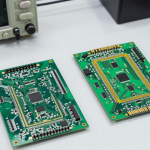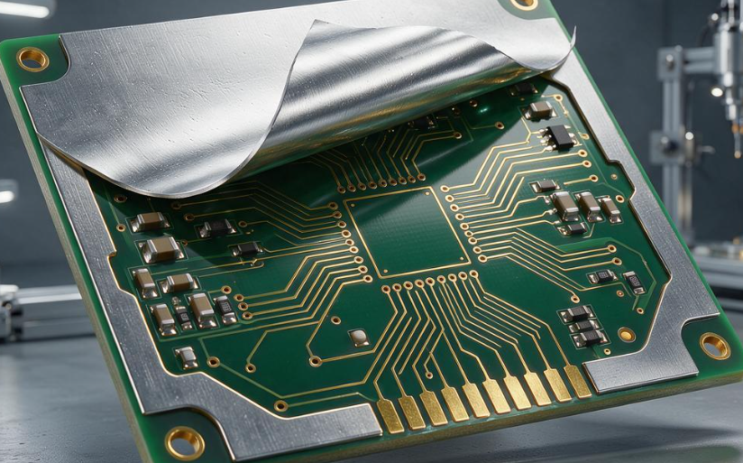
In many PCB designs, excessive layer count does not necessarily come from having too many signal layers. It can also result from unnecessarily separating power and ground planes.
A common design habit is to assign one dedicated layer to each voltage rail or to physically separate every ground domain. While this approach can simplify certain aspects of routing, it can also consume valuable PCB layer resources when the electrical requirements do not actually require independent planes.
For some low-current, low-noise applications, power plane consolidation can reduce unnecessary layers by placing multiple compatible power networks on the same internal layer and separating them by routing geometry and appropriate clearances.
Similarly, ground plane consolidation may be possible when different ground domains do not require complete physical isolation.
However, consolidation is not automatically suitable for every PCB. High-current switching circuits, sensitive analog circuits, RF systems, safety-isolated power domains, and high-voltage circuits may require dedicated structures.
The correct objective is therefore not simply to reduce layer count, but to simplify the PCB stackup while maintaining signal integrity, power integrity, EMC performance, safety, thermal behavior, and manufacturing reliability.
1. Common Problems Caused by Excessive Power and Ground Layer Separation
One typical example is the use of independent internal layers for several low-current voltage rails such as 3.3 V, 1.8 V, and 1.2 V.
If these rails occupy separate layers despite having relatively low current demand, significant portions of each plane may remain unused. From a resource perspective, this can create an inefficient stackup.
Ground-layer duplication can create a similar situation. Some designs physically separate analog ground, digital ground, auxiliary ground, and power ground even when their electrical noise levels and system architecture do not require complete isolation.
This can increase:
- PCB layer count
- Material consumption
- Lamination complexity
- Drilling requirements
- Manufacturing cost
- Engineering and inspection effort
More importantly, simply adding more power or ground layers does not automatically improve electrical performance.
If power domains are poorly arranged, long current paths, narrow neck-downs, unnecessary transitions, or inadequate decoupling can still result in excessive power-distribution impedance.
Likewise, splitting ground planes without understanding signal return paths can force high-frequency return currents to travel around discontinuities, potentially increasing loop area, EMI, and crosstalk.
Therefore, the question should not be “How many power and ground layers can be added?” but rather “Which electrical functions actually require independent layers?”
2. Core Principles for Power and Ground Plane Consolidation
A successful PCB layer reduction strategy should evaluate power and ground consolidation according to the actual electrical requirements.
Principle 1: Separate Power Domains by Electrical Behavior
Not every voltage rail needs its own physical layer.
Low-current rails with compatible electrical characteristics can sometimes share an internal layer through clearly defined copper regions.
However, high-current power inputs, switching-node circuits, motor supplies, high-voltage domains, and sensitive RF power rails may require dedicated routing or plane structures.
Before consolidation, evaluate:
- Continuous and peak current
- Switching frequency
- Noise sensitivity
- Voltage level
- Return-current path
- Thermal requirements
- Safety isolation
- EMC requirements
Principle 2: Do Not Physically Split Ground Without a Clear Reason
A continuous ground reference is often valuable for high-speed signals.
If analog and digital grounds are physically separated without a carefully defined connection strategy, return currents may be forced into unexpected paths.
In many systems, controlled regional partitioning on a common ground plane can be more effective than creating multiple isolated ground layers.
However, precision analog, medical, RF, high-voltage, and other specialized applications may have different grounding requirements.
Principle 3: Consolidate Compatible Voltage Rails
Multiple low-current voltage rails can sometimes be placed on one internal power layer.
For example, 3.3 V, 1.8 V, and 1.2 V regions can be assigned to different areas of the same layer when:
- The current requirements are manageable
- Adequate clearance is maintained
- Power routing does not create excessive voltage drop
- Switching noise is controlled
- The layer remains compatible with the signal stackup
The actual clearance should follow the PCB manufacturer’s design rules and the relevant electrical/safety requirements rather than applying one fixed value to every project.
Principle 4: Preserve the Main Ground Reference
When power layers are consolidated, the ground reference should remain as continuous as practical.
This is particularly important for:
- High-speed differential pairs
- Clocks
- RF transmission lines
- Fast digital interfaces
- Sensitive analog signals
A continuous reference plane helps maintain a predictable return path and can reduce the loop area associated with high-frequency currents.
3. Practical Power Plane Consolidation for Multi-Voltage PCBs
For consumer electronics, industrial controllers, and other relatively low-current systems, multiple voltage rails may sometimes be consolidated onto one internal power layer.
A typical approach is to assign different copper regions to different voltage networks.
For example:
- Region A: 5 V
- Region B: 3.3 V
- Region C: 1.8 V
- Region D: 1.2 V
Each region should have a clearly defined boundary and sufficient clearance from adjacent networks.
The power regions should then be connected to the corresponding loads through appropriately sized traces or vias.
During optimization, engineers should verify:
- Voltage-drop margin
- Current density
- Via current capacity
- Copper area
- Thermal distribution
- Decoupling locations
- Switching-noise coupling
The objective is not to maximize the number of voltage regions on one layer. Excessive fragmentation can create narrow current paths and increase impedance.
A well-planned consolidation can potentially replace multiple lightly utilized power layers, but the achievable reduction depends on routing density and electrical requirements.
4. Practical Ground Plane Consolidation
Ground consolidation requires even greater attention to current return paths.
In many general-purpose digital systems, a continuous ground plane can provide a better reference structure than several fragmented ground layers.
Instead of creating separate physical ground layers for every functional block, engineers can use regional layout techniques:
- Place noisy switching circuits away from sensitive analog circuits
- Keep high-current loops compact
- Route sensitive signals over continuous reference copper
- Use appropriate filtering at domain interfaces
- Control where different current paths converge
- Add ground stitching where required
For mixed-signal designs, the important factor is not simply whether analog and digital ground copper share the same physical layer. Engineers should understand where the return currents actually flow.
For precision measurement systems, RF designs, or circuits involving very low-level signals, additional isolation structures may still be necessary.
5. Protect Signal Integrity During Layer Reduction
One of the most important considerations during power and ground consolidation is maintaining the original signal environment.
When a power or ground layer is removed, signal layers may become farther from their reference plane or may need to change routing layers.
This can affect:
- Characteristic impedance
- Return-path continuity
- Crosstalk
- Electromagnetic coupling
- Differential-pair balance
- EMI performance
For controlled-impedance interfaces, the revised stackup must be recalculated using the actual dielectric thickness, copper thickness, trace width, and dielectric constant.
A signal layer that previously referenced a nearby ground plane should not be left without an appropriate reference simply because the layer has been repurposed.
Therefore, PCB stackup optimization and signal-integrity analysis should be performed together.
6. Maintain Power Integrity After Consolidation
Reducing dedicated power layers does not automatically reduce power integrity.
In some cases, consolidating compatible power regions can actually simplify the current path and reduce unnecessary transitions.
However, engineers should verify:
- DC voltage drop
- Current distribution
- PDN impedance
- Decoupling effectiveness
- Power-plane resonance
- Transient response
- Via inductance
For high-speed processors and memory interfaces, the placement of decoupling capacitors can be more important than simply increasing the number of power layers.
A low-inductance path between the power pin, capacitor, ground via, and reference plane is essential for controlling high-frequency transient noise.
7. EMC Considerations During Power and Ground Consolidation
EMC design must also be considered when combining power and ground layers.
A poorly planned consolidation can create larger current loops or force high-frequency return currents through unintended paths.
Particular attention should be paid to:
- DC/DC converter switching loops
- Clock signals
- High-speed interfaces
- RF circuits
- Connector transitions
- Cable interfaces
- Board-edge currents
- Ground-plane discontinuities
Ground stitching vias can be used where appropriate to provide lower-inductance return paths and improve electromagnetic containment.
However, the number and spacing of stitching vias should be determined according to the actual frequency range, stackup, geometry, and EMC test requirements.
8. Copper Distribution and Thermal Reliability
Layer reduction also changes the distribution of copper throughout the board.
If several power layers are consolidated into one layer, the resulting copper density may become highly nonuniform.
This can influence:
- Resin flow
- Lamination balance
- Board thickness
- Warpage
- Local thermal behavior
For this reason, copper balance should be evaluated across the complete stackup.
High-current areas may require larger copper regions or additional thermal vias, while sensitive signal areas should maintain sufficient routing space.
The goal is to optimize electrical and thermal performance without creating manufacturing problems.
9. Verify the Revised Stackup Through DFM
Before releasing the optimized design for production, a detailed DFM assessment should be completed.
The review should include:
Stackup
Verify:
- Core and prepreg selection
- Dielectric thickness
- Copper thickness
- Layer symmetry
- Material availability
- Controlled-impedance requirements
Power Regions
Check:
- Clearance between voltage domains
- Current capacity
- Via density
- Copper neck-downs
- Thermal hotspots
Ground Structure
Check:
- Reference-plane continuity
- Signal return paths
- Ground stitching
- Connector transitions
- Potential plane splits
Manufacturing Capability
Confirm that the revised structure remains within the manufacturer’s qualified process window for:
- Line width and spacing
- Drilling
- Plating
- Lamination
- Board thickness
- Registration
- Surface finish
This ensures that PCB layer reduction does not create new production problems while solving the original cost issue.
10. Prototype and Reliability Validation
After consolidation, the revised PCB should be validated through representative prototypes.
Depending on the product, testing can include:
- Impedance measurement
- Power integrity testing
- Voltage-drop measurement
- Thermal testing
- EMC/EMI testing
- High-speed interface testing
- RF performance testing
- Mechanical testing
- Temperature cycling
- Humidity testing
- Assembly validation
For products operating under demanding environmental conditions, reliability validation should reflect the actual application environment.
The objective is to demonstrate that the optimized board continues to satisfy the required electrical, mechanical, thermal, and environmental specifications.
Conclusion
Power plane consolidation and ground plane consolidation can be useful methods for reducing unnecessary PCB layers, particularly when multiple low-current power domains or redundant ground structures consume layer resources without providing essential electrical functions.
However, consolidation should never be treated as a universal or zero-risk solution.
Engineers must first analyze current paths, signal references, impedance, EMC requirements, thermal behavior, safety constraints, and manufacturing capability.
When the revised PCB stackup is carefully designed and validated, layer reduction can simplify manufacturing while maintaining power integrity, a predictable return path, and long-term PCB reliability.
Kingda can support PCB layer-reduction projects through stackup analysis, power and ground-plane optimization, impedance verification, DFM review, prototype validation, and mass-production support.