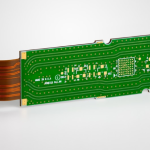
PCB Layout Quality: The Review Checklist Before You Release
Judging PCB layout quality is not a matter of taste. The same five areas decide the answer every time, and each of them can be inspected in a specific way rather than argued about. This is the checklist worth running before a file is released, because every item on it is cheaper to fix in the editor than after the boards arrive.
Start With the Planes
Open the file and inspect the power and ground layers before any routing. A copper pour that does not connect to its net is decoration; isolated islands carry nothing and can be removed in a thermal cycle. The design rules that govern the pour belong to the same layout review as the routing. Confirm that the pours are continuous and that the copper that has to carry current is wide enough for the current, allowing for the temperature rise the material can accept.
Then look for bottlenecks rather than widths. A broad pour that narrows to a thin neck at a pad, or that crosses a layer through a small group of vias, has a local resistance that the overall width hides. Check that the return path beneath every critical signal has reference plane integrity and is unbroken; a fast signal crossing a split in its reference plane forces the return current into a long detour, which raises emissions and coupling without changing a single trace.
Then the High Speed Routing
Impedance continuity comes first. Look at corners: a 45 degree or curved turn disturbs the field less than a right angle. Look at the number of vias in each net, and at whether the trace width changes along the way. Every abrupt change is a reflection point, and several of them in one net turn a clean eye diagram into a marginal one.
Length matching comes second, and it is a report rather than an impression. Open the constraint report for the matched groups and confirm that each group is inside its allowance. Then check where the compensation was added: serpentine sections placed near the package increase coupling exactly where the escaping signal density is highest, while the same length added near the far end achieves the timing without the penalty.
Third, look at spacing and orientation. Adjacent high speed traces need enough separation for the crosstalk budget, and traces on adjacent layers should run orthogonally where the layout permits, which keeps the broadside coupling low without extra routing effort.
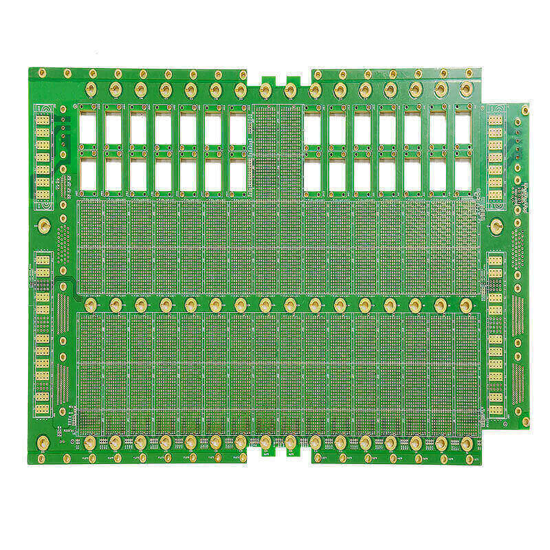
Placement Is an Electrical and a Manufacturing Question
Electrically, the placement should separate analogue from digital, high current from small signal, and heat sources from thermally sensitive parts. Those separations are what stop a switching node from sharing a ground return with a reference input.
For manufacturing, check the clearances the placement process needs. Fine passives such as 0402 parts need enough space between them for the nozzle and for reflow, and a component placed over a mounting hole or a tooling location is a mechanical interference that will be found by the mechanical team rather than by the electrical review. Confirm as well that every net that needs to be probed during bring-up has a test point that a probe can actually reach; a test point hidden under a tall component does not contribute to coverage.
Silkscreen Is Part of the Deliverable
Silkscreen is regularly ignored in quality reviews, and it is one of the cheapest things to get right. Silkscreen clarity is not a finishing touch, it is a functional requirement of the assembly drawing. Reference designators should be legible, consistently sized and not covered by the part they identify. Polarity marks on diodes and electrolytic capacitors should be unambiguous, and connector labels such as supply, ground and the two data lines should be printed where a technician will look for them.
The cost of a poor silkscreen is not aesthetic. It is a reworked board during assembly and a wasted afternoon during debugging, both of which are avoided entirely at the layout stage.
Compliance With the Process
The last area is what the fabrication and assembly processes actually require, and it is the area where DFM compliance is decided. Minimum trace width and spacing have to sit inside the fabricator capability for the copper weight being used, and the solder mask openings have to match the pads: too generous and the assembly process has more exposed copper to bridge, too tight and the paste release suffers. Consider whether vias need to be tented or plugged, because an open via next to a pad can draw solder away during reflow. Check that routed slots and V-score lines avoid component pads, since a board that separates along a line crossing a pad cannot be assembled. Confirm the minimum feature sizes against the fabrication capability the supplier actually offers.
None of these are opinions, and none of them require a second reviewer to be senior. They require the design to be checked against the capability of the supplier that will build it, which is a conversation that belongs before the file is released rather than after the panels are made.

Running the Review
Work in a fixed order: planes, then high speed routing, then placement, then markings, then process compliance. A fixed sequence is what stops a review from depending on the mood of the reviewer that day. Fix the order and the review stops being a matter of what the reviewer happens to remember. Record what was checked and what was assumed, and repeat the manufacturing review with the fabrication team, so the next revision knows which conclusions still hold and which have to be revisited because the stack-up or the supplier changed.
A useful final pass is to open the file with the intent of criticising it rather than confirming it. Look for the neck in the pour, the via count on the matched net, the reference designator under the connector, the pad that the V-score crosses. Those four items account for a large share of the problems that reach production, and all four are visible without a single measurement. The test coverage your programme needs should also be confirmed at this point, because adding a test point later is a board revision.
FAQ
Does every net need a test point? Every net the bring-up and production test plan needs to reach, and the plan should be written before the layout is finished.
How much crosstalk spacing is enough? Enough for the budget, which depends on the edge rate and on the layer. A fixed multiple of trace width is a starting point, not an answer.
Can a design be too densely packed? Yes. Density that pushes the assembly process outside its capability converts an electrical success into a yield problem.
Who should perform the review? Someone other than the designer, working from the same checklist, because the designer has already decided what is acceptable.
Summary
PCB layout quality is assessed on five areas: continuous planes and adequate current paths, high speed routing with controlled impedance and matched length, placement that respects both the electrical and the assembly requirement, legible and correct markings, and compliance with the fabrication process. Check them in that order, record the outcome, and the review becomes repeatable instead of personal.