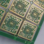
How PCB Factories Cut Prototype Production Time
Prototype production time is the interval between a released fabrication package and a box of working boards on the bench. For most hardware teams it is the most expensive delay in a project, because every extra week pushes schematic verification, firmware bring-up, and compliance testing to the right. Fabricators that consistently ship prototypes in three to five days are not doing anything magical. They remove the non-technical minutes that pile up around imaging, drilling, plating, and routing, and they protect the technical steps from interruption.
Why a PCB prototype schedule slips
Prototype production time rarely grows because a machine is slow. It grows because work waits. A job sits in a queue while a question about the stackup is answered by email. A panel waits for a drill program that depends on a file exported with the wrong layer mapping. A plating line stops because material for the next job has not been pulled from stores. Each event is short on its own, but together they add days to a build.
Emergency orders make the effect worse. When a rush job appears, the shop has to re-plan everything behind it. If that re-plan is informal, technicians chase the work instead of running it, and both the rush job and the normal jobs lose time. The fix is a plan that absorbs the rush job without shuffling the whole floor.
Prepare everything that does not need a machine
The first rule is simple: no job should enter the line until every non-technical item is complete. That means reading the fabrication drawing and the fabrication notes together, not just the Gerber archive, and confirming the requirements before the job is released. Working out panel size, copper weight, surface finish, impedance tolerance, and certification requirements after the job has started almost always costs more time than a careful review would have taken.
Material planning belongs to this stage as well. Copper-clad laminate, prepreg, solder mask, and legend ink should be kitted and staged before the first drill program runs. If a job needs two shifts, the second shift has to be staffed and briefed in advance, not improvised at the end of the first. Treating preparation as part of the schedule rather than as overhead is the cheapest way to shorten prototype production time.

A released package should answer questions before they are asked. A short fabrication note that lists the stackup by copper weight and dielectric thickness, the finished thickness tolerance, the minimum annular ring, the surface finish, and the impedance targets removes several email round trips from every build.
Standardize design documentation
Design documentation is where most delays hide. When the drawing is ambiguous, the fabricator has to choose an interpretation, and a wrong interpretation costs a full rebuild. Standard templates help because they force the same parameters to be stated in the same place every time: layer count, dielectric thickness, copper weight, drill schedule, via treatment, and outline dimensions with tolerances.
The same principle applies to the fabrication data itself. Consistent layer naming, a single drill file per layer pair, and machine-readable notes reduce manual interpretation. For a first article, the engineer should also decide in advance how the boards will be tested. Naming the test coupon pattern, the acceptance criteria for the applicable IPC class, and the certificate of compliance expected on delivery saves a clarification cycle later.
Use quick-turn fabrication for the first article
Quick-turn fabrication exists to validate a design, not to supply production volume. The economics change completely when the goal is learning rather than unit cost. A shop that keeps a dedicated prototype line can run a panel through imaging and etching in hours rather than days, because that line is not competing with volume orders.
Volume is the wrong goal for the first article. If the design has a feature that is sensitive to the process window, such as a fine-pitch escape or a controlled-impedance differential pair, the prototype should be built with the same process that production will use. Otherwise the prototype validates a process that will never be used again. The right compromise is a small number of boards built on the real process, ordered in the quantity needed to cover rework and test.
Panel utilization and quantity decisions
Panel utilization influences both cost and schedule. A design that tiles efficiently on a standard panel can be built on a shorter line, because it needs fewer imaging and drilling steps per board and fewer handling moves. Re-arranging a small prototype into a tighter array is often worth a few hours of layout work, since it reduces cost per unit and the number of physical operations on the floor.
At the same time, under-ordering is a schedule risk. Boards are damaged in assembly, and a test setup can destroy a part before it yields useful data. Ordering enough pieces to cover two or three spares is cheaper than a second prototype run, which restarts the whole queue. A practical rule is to build at least ten percent spares for a hand-assembled board, and more when the assembly uses fine-pitch parts that are difficult to rework.

Quantity decisions should also account for the assembly route. If the board will be stenciled and reflowed, the paste stencil and the placement program are only worth setting up for a batch that covers the engineering build plus spares.
Protect the technical steps from interruption
Once a job is running, the goal is to keep it moving. Internal changeovers are the main source of lost time on a prototype line, and each one has a fixed cost in setup, warm-up, and first-article inspection. Grouping jobs that share a material or a drill program lets the shop amortize those costs across several orders instead of paying them per job.
Work instructions that travel with the job help here. If the traveler states the drill program, the plating thickness, and the inspection points, the operator does not need to leave the machine to find out. A well-prepared traveler is the difference between a line that runs and a line that waits for answers. For more on how early layout choices propagate into the shop, see layout decisions that affect production.
Communication checkpoints that save days
A short, scheduled status update is more useful than many unscheduled questions. Two checkpoints are usually enough: one when the data is accepted, confirming the stackup, the finish, and the delivery date, and one when the boards reach final inspection. Everything between those points should be quiet, because interruptions slow the line down.
When an issue does appear, it should be raised with a proposed solution rather than as an open question. If a controlled-impedance stackup is not available on the standard build, say so together with the two closest options and the expected effect on the schedule. That pattern keeps the decision moving and the job on the line. Background on data preparation is available in our guide to PCB design and fabrication.
Measure the real lead time
Reducing prototype production time requires knowing which step consumes it. Timestamping the job at data acceptance, tooling release, drill, plating, routing, electrical test, and shipment turns a vague schedule into a measurable process. Most shops discover that queue time dominates, and that the queue is driven by missing information or missing material rather than by machine capacity.
With that data in hand, the improvements tend to be unglamorous: a stricter data acceptance check, a kitted material cart for prototype jobs, a traveler that answers questions in advance, and a rule that rush jobs are scheduled rather than inserted. None of these requires new equipment, and together they can remove several days from a typical build. Teams that standardize the first article also find that their multilayer prototype requirements become easier to review, because the same parameters are checked every time.
FAQ
How long should a prototype take? A two- to four-layer prototype with standard materials can be built in three to five working days when the data is complete on arrival. Layer counts above eight, heavy copper, or an unusual surface finish add one to three days for tooling and process setup.
Does ordering more boards slow the build down? Not meaningfully, as long as the order still fits the same panel. Beyond that point the shop needs additional panels plus extra drilling and plating time, so a large jump in quantity is where prototype production time starts to grow.
What causes most delays? Incomplete or ambiguous design documentation, followed by material that was not staged. Both are preparation problems, and both are solved before the job ever reaches the line.