PCB Resistors: Types, Functions, Applications, Identification, and Selection Guide
PCB resistors are among the most fundamental components used in modern electronic devices. Almost every printed circuit board (PCB) contains a combination of active components, such as transistors and integrated circuits (ICs), and passive components, such as capacitors and resistors.
Although resistor design involves detailed electrical calculations and circuit analysis, this guide focuses primarily on how resistors are used on PCBs, why they are needed, the different types available, how to identify them, and how to select the right resistor for a specific application.
The basic operating principle of a resistor is described by Ohm’s Law (V = IR). Resistors control current, divide voltage, establish bias conditions, match impedance, and dissipate electrical energy as heat. Without appropriate resistance, many circuits would draw excessive current, potentially causing component damage or circuit failure.
Because different PCB applications require different electrical and mechanical characteristics, resistors are available in many configurations, packages, resistance values, tolerances, and power ratings.
What Is a PCB Resistor?
A PCB resistor is a two-terminal passive electronic component designed to oppose and control the flow of electric current within a printed circuit board. By providing a precisely defined resistance, it allows engineers to control voltage and current throughout a circuit.
Resistors can be installed on PCBs using either through-hole technology (THT) or surface-mount technology (SMT). Through-hole resistors use leads inserted through drilled PCB holes, while surface-mount resistors are soldered directly onto conductive pads on the PCB surface.
PCB resistors perform many important functions. For example, they can:
- Limit current flowing through LEDs and other sensitive components
- Create voltage-divider circuits
- Establish transistor bias conditions
- Provide pull-up and pull-down functions
- Match transmission-line impedance
- Terminate high-speed signal paths
- Dissipate electrical energy
- Control analog signal levels
- Protect sensitive components from excessive current
This versatility makes resistors indispensable in virtually every category of electronic equipment.
Functions of PCB Resistors

A resistor does much more than simply “reduce current.” Depending on how it is connected, it can perform several different electrical functions.
1. Voltage Division
Two or more resistors connected in series can create a voltage divider.
For two resistors, the output voltage can be calculated as:
Vout = Vin × R2 / (R1 + R2)
This configuration is widely used to generate reference voltages, scale sensor outputs, and adapt voltage levels between different circuit sections.
For example, a voltage-divider network can reduce a 5 V signal to approximately 3.3 V for a lower-voltage IC input, provided the circuit’s loading conditions are properly considered.
2. LED Current Limiting
LEDs require controlled current to operate safely. Connecting an appropriate resistor in series with an LED limits current and prevents excessive current from damaging the device.
The required resistance can be estimated using:
R = (Vsupply − VLED) / ILED
The resistor’s power rating must also be checked to ensure that it can safely dissipate the resulting heat.
3. Heat Dissipation
A resistor converts part of the electrical energy it receives into heat.
Its power dissipation is calculated as:
P = VI = I²R = V²/R
This principle is intentionally used in applications such as power resistors, load banks, braking circuits, heaters, and certain temperature-control systems.
However, excessive power dissipation can cause the resistor temperature to rise beyond its rated limit. Therefore, engineers must consider both resistance value and power rating.
4. Impedance Matching and Signal Termination
Resistors are also important in high-speed digital, RF, and communication circuits.
A properly selected termination resistor can reduce signal reflections caused by impedance discontinuities. This helps preserve signal integrity and reduce ringing, overshoot, and other waveform distortions.
For high-speed PCB designs, resistor selection should therefore be considered together with:
- Trace impedance
- Transmission-line length
- Driver impedance
- Receiver characteristics
- Signal rise time
- PCB stackup
- Operating frequency
Types of PCB Resistors


PCB resistors can be classified according to their construction, resistance characteristics, adjustability, and intended application.
1. Linear Resistors
Linear resistors generally maintain a predictable relationship between voltage and current within their specified operating range.
Fixed Resistors
Fixed resistors have a predetermined resistance value that cannot normally be adjusted during operation.
They are the most common resistor type used in PCB designs and are widely used for:
- Current limiting
- Voltage division
- Pull-up and pull-down circuits
- Transistor biasing
- Signal termination
Variable Resistors
Variable resistors allow their resistance to be adjusted mechanically.
Common examples include:
- Potentiometers — three-terminal components commonly used for adjustable voltage division.
- Rheostats — variable resistors generally used as two-terminal current-control devices.
- Trimmer potentiometers — small adjustable resistors designed primarily for calibration and infrequent adjustment.
Trimmers are particularly useful when a circuit needs to be calibrated after PCB assembly.
2. Nonlinear Resistors
Unlike conventional fixed resistors, nonlinear resistive components change their electrical characteristics depending on voltage, current, temperature, or another external condition.
Examples include:
- Thermistors
- Varistors
- Photoresistors
Their resistance does not follow a simple constant V/I relationship across the full operating range.
3. Special-Purpose Resistors
Special-purpose resistive components respond to environmental conditions and are commonly used for sensing and protection.
Thermistors
A thermistor changes resistance according to temperature.
The two most common types are:
- NTC (Negative Temperature Coefficient): Resistance decreases as temperature increases.
- PTC (Positive Temperature Coefficient): Resistance increases as temperature increases.
Thermistors are used for temperature sensing, thermal protection, inrush-current limiting, and battery-management systems.
Photoresistors
A photoresistor, also called a light-dependent resistor (LDR), changes resistance according to the intensity of incident light.
Its resistance generally decreases as the amount of light increases.
How to Identify Resistors on a PCB

PCB resistors are commonly divided into through-hole resistors and surface-mount resistors.
Understanding their physical appearance and markings makes it easier to identify component values during PCB assembly, troubleshooting, and repair.
1. Through-Hole Resistors
Traditional through-hole resistors usually have colored bands printed around their cylindrical bodies.
Common configurations include:
- Four-band resistors
- Five-band resistors
- Six-band resistors
For a standard four-band resistor, the first two bands represent the significant digits, the third band represents the multiplier, and the fourth band represents tolerance.
For example, a resistor marked with:
Brown – Black – Red – Gold
has:
- First digit: 1
- Second digit: 0
- Multiplier: ×100
- Tolerance: ±5%
Therefore:
10 × 100 = 1,000 Ω = 1 kΩ ±5%
When reading a resistor, the tolerance band is normally positioned toward the right, with the significant-value bands read from left to right.
2. Surface-Mount Resistors
SMD resistors are compact components designed for automated PCB assembly.
They generally appear as small rectangular components with conductive metal terminals at both ends. Unlike through-hole resistors, they do not require leads passing through PCB holes.
SMD resistors are placed directly onto PCB solder pads using surface-mount technology (SMT).
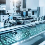
During mass production, a pick-and-place machine accurately positions the components on solder paste-covered pads. The PCB then passes through a reflow soldering oven, where the solder paste melts and forms permanent electrical and mechanical connections.
SMD resistors are especially advantageous for:
- Compact PCB layouts
- High component density
- Automated assembly
- High-volume manufacturing
- Lightweight electronic products
Applications of PCB Resistors
PCB resistors are used throughout electronic circuits to control current, establish voltage levels, protect components, and maintain signal integrity.
1. Current Limiting and Circuit Protection
One of the simplest resistor applications is limiting current.
For example, a resistor connected in series with an LED prevents excessive current from flowing through the LED.
Resistors are also frequently used around transistor bases, gate-drive circuits, and other semiconductor devices to control current and establish appropriate operating conditions.
2. Voltage Divider Networks
Two or more resistors can be connected in series to produce a desired fraction of an input voltage.
Common applications include:
- Voltage-level conversion
- Sensor signal conditioning
- Reference-voltage generation
- Analog measurement circuits
- Battery-voltage monitoring
For example, a resistor divider can scale a higher battery voltage into a safe measurement range for a microcontroller ADC.
3. Bias Networks
Resistors establish appropriate DC voltage and current conditions for transistors, operational amplifiers, and other analog circuits.
A properly designed bias network keeps an active device within its intended operating region and helps establish stable quiescent operating conditions.
4. Pull-Up and Pull-Down Networks
Digital circuits frequently use resistors to establish a defined logic state.
A pull-up resistor connects a signal line to a positive supply, while a pull-down resistor connects it to ground.
These configurations are commonly used with:
- Microcontrollers
- Digital inputs
- Switches
- I²C interfaces
- Logic circuits
5. Signal Termination
High-speed digital interfaces can use termination resistors to minimize signal reflections and improve waveform quality.
This is particularly important in high-speed PCB applications involving fast edge rates, long traces, and controlled-impedance transmission lines.
Common PCB Resistor Problems and Solutions
Although resistors are generally reliable, inappropriate component selection, excessive thermal stress, mechanical stress, and poor soldering can lead to failures.
1. Thermal Stress and Cracking
Repeated temperature changes cause PCB materials, solder joints, and electronic components to expand and contract at different rates.
This can create mechanical stress in the solder joints and eventually produce microcracks.
Potential symptoms include:
- Intermittent electrical connections
- Resistance instability
- Unexpected circuit resets
- Complete open circuits
Solution
Engineers should:
- Select an appropriate resistor power rating.
- Consider the resistor’s temperature coefficient.
- Maintain sufficient PCB copper area for heat dissipation.
- Avoid excessive thermal cycling.
- Consider component derating in demanding applications.
- Validate solder-joint reliability during qualification testing.
2. Thermal Drift and Overheating
When a resistor operates close to or beyond its rated power, its temperature rises.
Excessive temperature can cause:
- Resistance drift
- Permanent parameter changes
- Discoloration
- Cracking
- Complete component failure
A practical design should normally provide sufficient power margin rather than operating the resistor continuously at its maximum rated power.
3. Incorrect Resistance Value
Installing an incorrect resistor value can cause:
- Excessive LED current
- Incorrect bias conditions
- Wrong sensor readings
- Logic-level problems
- Signal distortion
- Excessive power dissipation
Therefore, resistor markings and component part numbers should be verified before assembly.
4. Poor Solder Joints
Insufficient solder, poor wetting, contamination, excessive heating, or incorrect reflow conditions can produce unreliable resistor connections.
For high-volume manufacturing, SPI, AOI, and electrical testing can help identify assembly defects.
How to Select the Right PCB Resistor
Selecting a resistor involves much more than choosing a resistance value.
Engineers should evaluate the following parameters.
1. Resistance Value
The resistance value must satisfy the circuit’s electrical requirements.
Ohm’s Law provides the starting point:
R = V/I
For a voltage-divider circuit:
Vout = Vin × R2/(R1 + R2)
2. Power Rating
The resistor must safely dissipate the heat generated during operation.
The basic relationship is:
P = V²/R
or
P = I²R
A resistor with insufficient power capacity may overheat or fail.
3. Tolerance
Tolerance defines how much the actual resistance can vary from its nominal value.
Common values include:
- ±1%
- ±5%
- ±10%
Precision analog circuits may require much tighter tolerance.
4. Temperature Coefficient
The temperature coefficient of resistance (TCR) describes how resistance changes with temperature.
Low-TCR resistors are preferred when resistance stability is important, such as in:
- Precision measurement circuits
- Instrumentation
- ADC reference networks
- Precision amplifiers
5. Package Size
Common SMD packages include:
- 0201
- 0402
- 0603
- 0805
- 1206
Smaller packages save PCB space but can be more difficult to inspect, rework, and manufacture.
6. Operating Voltage
A resistor also has a maximum working-voltage rating. A resistance value may satisfy the power requirement while still exceeding the resistor’s allowable voltage.
Therefore, both power rating and voltage rating must be checked.
7. Application Environment
For automotive, industrial, medical, aerospace, and other demanding applications, engineers should consider:
- Operating temperature
- Humidity
- Vibration
- Chemical exposure
- Long-term reliability
- Component qualification requirements
How to Solder a Resistor to a PCB
For through-hole components or manual rework, resistor soldering can be completed through a straightforward process.
Step 1: Prepare the Required Tools
Typical tools include:
- Soldering iron with temperature control
- Solder wire
- Flux
- Solder wick or desoldering pump
- Tweezers
- PCB holder
- Cleaning materials
- Appropriate personal protective equipment
For SMD resistor assembly, automated SMT equipment is normally preferred in production environments.
Step 2: Prepare the PCB
Before soldering:
- Inspect the PCB.
- Clean the solder pads if necessary.
- Verify the resistor value.
- Confirm the component orientation if applicable.
- Preheat the soldering iron to an appropriate temperature.
Clean solder pads help ensure proper solder wetting and reliable joints.
Step 3: Install and Solder the Resistor
For a through-hole resistor:
- Insert the component leads through the correct holes.
- Hold the component securely.
- Heat both the PCB pad and resistor lead.
- Apply solder to the heated joint rather than directly to the soldering-iron tip.
- Allow the solder to flow around the joint.
- Remove the solder and then the iron.
- Allow the joint to cool naturally.
- Trim excess leads.
A good solder joint should have proper wetting, sufficient solder coverage, and a secure mechanical connection.
For SMD resistors, solder paste, component placement, and reflow-profile control are generally used in production.
PCB Resistor Selection Checklist
Before finalizing a resistor for a PCB design, engineers should verify:
| Parameter | What to Check |
|---|---|
| Resistance | Required nominal resistance |
| Tolerance | Maximum acceptable variation |
| Power Rating | Expected power dissipation and design margin |
| Voltage Rating | Maximum voltage across the resistor |
| TCR | Resistance stability over temperature |
| Package | Available PCB space and assembly process |
| Operating Temperature | Environmental requirements |
| Reliability | Expected operating lifetime |
| Application | Consumer, industrial, automotive, medical, aerospace, etc. |
| Availability | Supply-chain stability and lifecycle status |
For production PCB designs, engineers should also consider component availability, approved-vendor lists, alternative part numbers, and long-term supply stability.
PCB Resistors: Frequently Asked Questions
What is the main purpose of a resistor on a PCB?
The primary purpose of a resistor is to control current and voltage. Depending on its configuration, it can also perform voltage division, biasing, signal termination, impedance matching, protection, and sensing functions.
What is the difference between a through-hole resistor and an SMD resistor?
A through-hole resistor has leads that pass through PCB holes, while an SMD resistor is mounted directly onto PCB surface pads. SMD resistors are smaller and better suited to automated, high-density PCB assembly.
How do I calculate resistor power?
You can calculate resistor power using:
P = VI
P = I²R
or
P = V²/R
The calculated power should be compared with the resistor’s rated power, while allowing an appropriate design margin.
Why do resistors get hot?
A resistor converts electrical energy into heat. If the circuit causes it to dissipate significant power, its temperature will increase. Excessive heating may indicate that the resistor’s power rating is insufficient for the application.
Can a resistor fail on a PCB?
Yes. Common causes include excessive power, overheating, mechanical stress, solder-joint cracking, incorrect component selection, electrical overstress, and long-term environmental exposure.
Conclusion
PCB resistors may be among the simplest components in an electronic system, but they perform some of the most important functions in circuit design. They regulate current, divide voltage, establish bias conditions, protect sensitive components, control signal levels, and improve signal integrity.
Selecting the correct resistor requires more than simply choosing a resistance value. Engineers must consider resistance, tolerance, power rating, voltage rating, temperature coefficient, package size, operating temperature, reliability, and application requirements.
As PCB designs continue to become smaller, faster, and more complex, resistor selection is increasingly connected to overall PCB design, signal integrity, thermal management, and manufacturing reliability. By selecting the appropriate resistor and validating its electrical and thermal performance, engineers can improve circuit stability and achieve reliable long-term operation.