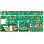
PCB Size and Shape Requirements: Defining the Board Outline
A printed circuit board has to fit the application it was designed for, and the application dictates the size and the shape. That sounds obvious, yet the outline is often the last thing to be finalised and the first thing to force a redesign, because it is the one part of the layout that the electrical designer does not own. Settling it before layout begins is the cheapest hour in the project.
Why the Outline Comes First
Aggressive schedules push designers to start placing components before the mechanical information arrives, and the result is predictable. A processor is placed at the centre of the available area and then a mounting hole turns up exactly where its decoupling capacitors need to be, or a connector is positioned against an edge that later moves. Changes of this kind are not small, because they touch placement, routing and sometimes the stackup. Beginning with a complete picture of the outline data avoids the situation where a mid-project change invalidates work that has already been done, and it costs far less than the alternative.
What to Collect Before Layout
The information needed is not only the length and width of the board. It includes every feature that constrains where a component may sit: mounting holes and their associated keep-out, the position of connectors that must align with openings in the enclosure, the height restriction above and below the board, the areas where the enclosure contacts or supports the board, and any region that must remain free of copper for mechanical or regulatory reasons. These details come from the mechanical design, so collecting them means working with the mechanical engineer rather than assuming the answer, and the questions are worth asking early and asking repeatedly. The same information determines the outline itself and the constraints that will later be applied during routing, and it is the reason outline and mounting design are treated as one subject, as described in this article on board outline and mounting design.

Methods for Creating the Outline
Once the data is available, the outline can be created in several ways. A drawing utility allows the outline to be drawn manually, together with the additional closed shapes that define keep-outs and routing constraints; the drawing tools can then be used to add arcs, chamfers and other features until the shape matches the mechanical design. Many design systems also provide a wizard that creates the outline automatically and, as part of the same operation, generates the initial layer stackup and the default trace width and spacing values. The wizard saves time on a straightforward rectangular board, and its output still has to be checked against the mechanical drawing.
Importing Mechanical CAD Data
For anything other than a simple rectangle, the most reliable method is to import the outline from the mechanical design rather than to redraw it. Mechanical CAD data can be supplied in several formats, including DXF, IDF, IDX and the IPC-2581 standard, and the design system reads the imported geometry and constructs the board outline from it. Importing removes transcription errors and keeps the electrical and mechanical models consistent when the enclosure changes. An outline that is likely to be reused can also be saved as a template, which is useful for a product family where a common form factor appears in several designs. The practical requirement is a CAD system that supports the formats the mechanical team actually uses, which is worth confirming before the project starts rather than after the data arrives.

Height Restrictions and Three-Dimensional Checks
A two-dimensional outline is not sufficient on a dense board. Components have height, the enclosure has a lid, and a connector may need clearance for a mating part. Height restrictions have to be recorded as part of the outline data, both above and below the board, and they should be expressed as limits over defined areas rather than as a single figure for the whole board. Where the design system can display the board in three dimensions alongside the mechanical model, the placement can be checked interactively and interference found while it is still a placement problem rather than a routing problem. This is also the stage at which the clearance between the board edge and nearby components is checked, since a part that overhangs the outline can conflict with the enclosure or with a neighbouring board.
From Outline to Stackup and Routing Constraints
The outline is not the only constraint generated at this stage. The board size and the mechanical environment influence the layer stackup, because a larger board moves more during processing and a thinner board is more flexible under vibration. The same exercise fixes the position of the keep-outs, which then limit where traces and planes may run. Defining the outline and the stackup together keeps the two consistent, and the options are described in this article on layer stackup from one to eight layers. Because these decisions fix the manufacturability of the design as well as its fit, they are among the layout choices that carry directly into production, as described in this article on how PCB layout decisions affect production.
Documenting and Freezing the Outline
The outline data should be recorded in a form that survives the project. A dimensioned drawing, the source mechanical file, the keep-out definitions and any height restriction should be part of the released documentation, along with a note of the revision they came from. When the mechanical design changes, the outline file changes with it, and the board should be re-checked against the new geometry rather than patched locally. A design whose outline can be traced back to a specific mechanical revision is much easier to revise than one where the shape was drawn by hand and never recorded.
Keeping the Outline Under Control
The outline is a shared object between two disciplines, and it is most useful when both treat it as a controlled document rather than a sketch. The mechanical engineer should provide the geometry, the height envelope and the keep-out areas as a released file rather than as a drawing to be measured, and the electrical designer should confirm what was imported and record the revision it came from. Where the enclosure is still evolving, the board should be built with margin around the features that are most likely to move, such as connector openings and mounting holes, so that a small change does not force a re-layout. It also helps to keep the outline on a single layer with a clear name, since an outline duplicated across several layers is a frequent source of confusion when the data is prepared for fabrication. A short review of the imported geometry against the mechanical drawing before placement begins takes minutes and catches the errors that would otherwise be found by the enclosure.
FAQ
Can layout start before the outline is final? Placement of the power section and the main devices can begin, but routing should wait. A late change to the outline invalidates routing far more often than it invalidates a block placement.
Which format should be used to import a board outline? Whichever the mechanical team can export reliably. DXF and IDF are common, and IPC-2581 carries more information when the two disciplines exchange full designs.
Do height restrictions need to be recorded if the enclosure has plenty of room? Yes. The available height above a component varies across the board even in a generous enclosure, and the restriction is what allows a tall part to be placed without a later conflict.