Thermal Cycling Test Setup For PCB Reliability
Thermal cycling is the standard accelerated test for solder joint and plated hole reliability. The assembly is taken repeatedly between two temperature extremes, and damage accumulates at the interfaces where materials with different expansion coefficients meet. The value of the test depends entirely on how carefully it is set up.
A test that is too mild proves nothing, and one that is too severe produces failures that would never occur in service. The parameters that matter are the temperature range, the dwell time at each extreme, the ramp rate and the way the parts are monitored while the test runs.
What The Test Is Meant To Reveal
The damaging mechanism is differential expansion. Copper, solder, laminate and component bodies expand by different amounts as the temperature changes, and the joints and plated barrels absorb the difference. Over many cycles the solder cracks, a barrel fractures, or a pad lifts from the laminate.
Because the damage accumulates rather than appearing at once, the test measures a lifetime rather than a strength. Two designs can both pass a short test and still show very different numbers of cycles to failure, and it is that number which ranks them.
Temperature Range And Dwell Time
The range is chosen from the application. Consumer electronics is often tested between minus 40 and plus 125 C, while automotive and industrial products may extend to plus 150 C. A wider range produces more damage per cycle because the expansion difference is proportional to the temperature change.
The dwell time is the period held at each extreme, and it must be long enough for the whole assembly to reach the chamber temperature. A heavy board or a large component can take many minutes to soak, and a dwell that is too short leaves the interior at an intermediate temperature and understates the damage. The way the joint is built is described under lead-free versus leaded solder.
Ramp Rate And Chamber Loading
The ramp rate affects the result in a less obvious way. A fast ramp produces a larger temperature difference between the surface and the interior of the assembly, and therefore more strain per cycle, so a test run at a fast ramp is more severe than the same test run slowly.
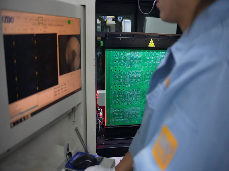
Chamber loading changes the effective ramp as well. A chamber filled with product cannot heat or cool as quickly as an empty one, so the programmed ramp is not the ramp the parts actually see. The chamber should be loaded consistently between runs, and the real profile should be measured with thermocouples on a representative sample.
Daisy Chain Monitoring
A daisy chain turns the joints under test into a continuous resistor by connecting them in series through the board. Monitoring the resistance continuously during the test detects a crack the moment it opens, and recording the cycle number gives the failure point directly without stopping the chamber.
Intermittent failures are the difficult case, because a joint may open for a few microseconds and reclose. Detecting them requires a fast event detector rather than a periodic resistance reading, and the event threshold has to be set low enough to catch a partial crack before it becomes a full open.
Failure Criteria And Inspection
Failure criteria should be stated before the test starts. A common definition is a resistance rise above a set threshold sustained for a defined period, or a single event above a higher threshold. Without a written criterion, different observers will call the same result differently.
Destructive inspection supports the electrical result. Cross sections of the joints and of the plated holes show where the crack initiated and how far it had propagated, and that information is what allows a design change to be targeted rather than guessed. The related acceptance work is described under PCB design quality characteristics.
Sample Size And Reporting
Sample size determines how much confidence the result carries. Reliability predictions are usually based on a Weibull treatment of the failure distribution, which needs enough failures to fit a slope; a test in which nothing fails simply sets a lower bound on the lifetime.
The report should record the chamber profile, the loading, the monitoring thresholds, the number of samples, the failures and the inspection findings. A result quoted without the profile is not comparable with anything else. How the test requirement is defined with the customer is described under PCBA development process.
Process Control and Verification
On a design of this kind, dwell time is the item that decides how the rest of the board is arranged. The process window is set by the narrowest step in the flow, so an improvement anywhere else shows up as margin rather than as yield until that step is addressed. A short note on the drawing about handling, storage or packaging is often worth more than an extra decimal place on a tolerance.
Where a value sits close to a process limit, the drawing should say so, since the shop can then open the process window rather than working to a nominal figure that carries no tolerance. A stack-up that is drawn rather than described removes most of the ambiguity from a quotation, and it lets the fabricator price the board against the dielectric and copper weights that will actually be used.
Where the requirement is not written down, the shop supplies its own default, and the default is chosen for the process rather than for the design.
Process Control and Verification
On a design of this kind, dwell time is the item that decides how the rest of the board is arranged. The process window is set by the narrowest step in the flow, so an improvement anywhere else shows up as margin rather than as yield until that step is addressed. A short note on the drawing about handling, storage or packaging is often worth more than an extra decimal place on a tolerance.
Where a value sits close to a process limit, the drawing should say so, since the shop can then open the process window rather than working to a nominal figure that carries no tolerance.
Process Control and Verification
On a design of this kind, dwell time is the item that decides how the rest of the board is arranged. The process window is set by the narrowest step in the flow, so an improvement anywhere else shows up as margin rather than as yield until that step is addressed. A short note on the drawing about handling, storage or packaging is often worth more than an extra decimal place on a tolerance.
A first article check confirms that the process and the drawing agree on the points listed above, and that the coupon data supports the values used in the design.

Where a measurement falls outside the expected window, the sample is retained so that the cause can be established before the balance of the batch is released.
FAQ
How many cycles are enough? It depends on the standard and the product. Many specifications use 100 cycles as a qualification screen and 500 to 1000 cycles for a lifetime study, but the number should follow from the expected service life rather than from habit.
Is thermal shock the same as thermal cycling? No. Thermal shock uses liquid to liquid transfer and produces very fast ramps, which is a harsher test aimed at different failure modes. Thermal cycling in air is the more common reliability test.
Why measure the chamber if it is programmed? Because the programmed profile is not the profile the product experiences. Loading, airflow and chamber condition all shift the real curve, and only a measured profile shows what the samples actually saw.