PCB Warpage Control in Assembly
Warpage is the change in a board’s shape when it is heated, and it is one of the few assembly problems that begins in fabrication and ends in the printing and placement equipment. A panel that is flat at room temperature can bow or twist enough at reflow temperature to lift a corner off the printer support, shift a pad under the placement nozzle or fail to sit flat in a test fixture. Because the effect is thermal, it is invisible in incoming inspection and appears only where it is least convenient.
What Causes Warpage
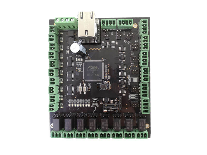
The primary cause is a mismatch in the thermal expansion of the materials within the stack. Copper and laminate expand at different rates, and the balance between copper distribution, prepreg content and layer symmetry determines whether the board bends when it is heated. Asymmetric stackups are the classic case: a board with heavy copper on one side and a thin plane on the other will bow in a predictable direction. Copper thickness and stackup balance are the design levers that control it.
Moisture is the second cause. Laminate absorbs water from the air, and the absorbed water expands when the board is heated, which adds stress to the same imbalance and can also cause local swelling. A board that has been stored in a humid environment behaves differently from one that came out of a dry store, which is why the same product can show different warpage in summer and winter. Baking before assembly is the standard countermeasure where the effect is significant.
Measuring and Specifying Flatness
Flatness is measured on a granite table or with a coordinate measuring machine, and the specification is usually expressed as a maximum deviation over the diagonal or as a percentage of the panel length. The measurement should state the condition of the board: before or after reflow, in which direction and with which support. A number quoted without those conditions cannot be compared with anything, which is why warpage arguments between customer and supplier are so often unresolvable.
The relevant measurement for assembly is the one taken at temperature, because that is the state in which the board meets the printer and the conveyor. A board that meets the flatness specification at room temperature and bows at two hundred degrees is a problem for assembly even though it conforms on receipt. Measuring at elevated temperature requires more effort, but the payback is a specification that predicts what actually happens. Panel design interacts with the specification because the panel size and the rail design affect how the board behaves.
Effect on Printing and Placement
Printing is the first process affected. A board that is not flat against the stencil leaves a gap, and the paste smears under the foil edge or fails to release cleanly. The defect appears at the position of the gap rather than uniformly, which makes it look like a stencil problem. Increasing squeegee pressure may mask it for a while, at the cost of stencil wear and paste smearing elsewhere.
Placement is affected when the board surface moves relative to the machine’s focal plane. Vision systems rely on fiducials to compensate for board position, and a bowed board means the fiducial is at a different height from the pads being placed, which reduces placement accuracy in the direction where support is missing. Where the effect is large, support pins or a vacuum plate restore the surface and the accuracy returns. Board edge and support clearance determines how much support can be applied.
Support in the Printer and Placement Machine
Support is the practical answer to warpage at the assembly stage. Under-board support pins, a machined support plate or a vacuum chuck hold the board flat during printing, and a similar arrangement is used in placement and in some reflow carriers. The support plan should be based on the measured shape of the board rather than on a standard pattern, because the high points of a twisted panel are not where a generic layout puts its pins.
Vacuum support is particularly effective for thin boards, because it holds the whole surface rather than a set of points. Adding support costs setup time and requires storage for the plates or profiles, and it should be justified against the alternative of accepting a lower yield. Where a product runs for years, a dedicated support plate is almost always worth the investment. Panel rail design also contributes, since a wider rail is stiffer and less prone to distortion.
Reflow and the Thermal Profile
Warpage is greatest at the temperatures where the laminate softens and the expansion is largest, which is exactly the range where the solder is molten. A board that bows at that moment can produce joint defects even when every other parameter is correct, because the component and the pad are no longer coplanar. For area array packages the effect is particularly damaging, since a ball that lifts a few tens of microns loses contact with its pad.
The profile influences the magnitude of the effect: a slower ramp gives the board more time to reach a uniform temperature and reduces the through-thickness gradient, which in turn reduces bending. Slower cooling has a similar benefit, since the differential contraction is the mirror image of the expansion. Where warpage is the limiting defect, adjusting the profile is often cheaper than changing the design, although it lengthens the cycle. Inspection strategy should include the joints most affected by the movement.
Reducing Warpage by Design
Design decisions made long before assembly determine most of the warpage. A balanced stackup with symmetric copper distribution and even prepreg content is the foundation. Avoiding large areas of copper on one side only, keeping the copper balance within a stated tolerance and selecting a laminate appropriate to the board thickness all reduce the tendency to bow. Where the board is thin and large, the panel rails and the position of the board within the panel matter as well.
The specification should also state what the assembly process can tolerate. A flatness limit that is tighter than the process needs adds cost without benefit, while one that is looser than the printing support can accommodate guarantees problems. Agreeing that limit with the fabrication supplier, and measuring it in the same way, is the only route to a specification that both parties can satisfy and verify.
Additional Considerations for This Build
Practical attention to coplanarity pays for itself here, because it decides whether the finished board behaves as the drawing intended. Where the requirement is not stated on the fabrication drawing or in the assembly notes, the shop has to assume a default, and that default is rarely the value the design was simulated with. Stating coplanarity explicitly, together with the tolerance that applies, removes the assumption and keeps the result predictable from batch to batch.
Process Control and Verification
On a design of this kind, reflow is the item that decides how the rest of the board is arranged. Where the requirement is not written down, the shop supplies its own default, and the default is chosen for the process rather than for the design. The measurements that matter are the repeatable ones: conductor width and spacing, annular ring, finished hole size, plating thickness and surface finish are all verifiable on a coupon that travels with the panel.
FAQ
Why does warpage appear only at reflow? Because the board is measured at room temperature in most inspections. The mismatch that causes bending only produces significant movement when the materials expand.
Can baking fix a warped board? Baking removes moisture that contributes to the movement, but it cannot fix an unbalanced stackup. Where the cause is the design, the fix is in the design.
What is a reasonable flatness limit? One derived from what the printer, the placement machine and the fixture can accommodate. It should be measured under the same conditions as the process.
Does panel size affect warpage? Yes. Larger panels are less stiff and bend more, which is one reason panel design and support planning belong together.