PCBA Production Flow from Bare Board to Finished Assembly
A bare printed circuit board becomes a functional assembly through a sequence of steps that each add material, components or information. The sequence matters because the order is fixed by physics: paste must be printed before parts are placed, parts must be placed before the alloy is melted, and firmware is usually loaded only after the hardware is known to be sound. This is how the PCBA production flow actually runs.
Stencil Printing
Solder paste is printed through a stainless steel stencil onto the pads. The paste must be at working temperature and the correct viscosity, and the stencil must sit flat against the board so that paste is deposited rather than smeared.
Printing is the step that most often decides the quality of the whole build, because a deposit that is wrong cannot be corrected later. Many lines now measure paste volume automatically after printing rather than waiting to inspect the joint, which turns a downstream defect into an immediate process correction.
Placement
The placement machine picks components from feeders with a vacuum nozzle and positions them on the printed pads according to the program. Modern machines place thousands of parts per hour with the vision system correcting position and rotation as each part is picked.
Accuracy is verified against fiducials on the board, which is why those marks must be present and unobstructed. Components that arrive on tape must be presented at the correct pitch, and the feeder setup is what makes that happen; the feeder is also the source of most placement errors on a high mix line.
<img src="https://www.gopcba.com/wp-content/uploads/2024/09/f67cc2b7e36fc7927cc10ee07b9359c-2048×1536-1.webp" alt="PCBA production line with printer placer and reflow oven in sequence” />
Reflow
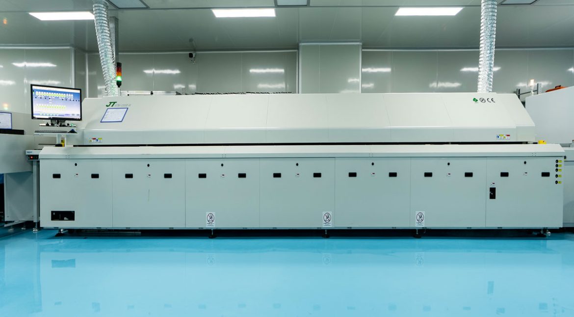
The board passes through a reflow oven with several independently controlled zones. The profile first warms the assembly to activate the flux, then soaks it to equalise temperature, then raises it above the melting point of the alloy and finally cools it at a controlled rate.
The peak temperature and the time above liquidus decide whether the joints form properly, and they must satisfy both the largest thermal mass on the board and the most heat sensitive component. After reflow, automated optical inspection checks for missing parts, displacement, tombstoning, wrong orientation, bridging and insufficient solder.

Through-Hole Insertion and Wave Soldering
Boards that carry through-hole components pass through a second soldering stage. Parts are inserted, either by hand or by an automatic insertion machine, and the board is then passed over a molten wave or soldered selectively with a small nozzle.
Wave soldering suits boards with many through-hole joints on one side, while selective soldering is used where a full wave would damage parts already placed on the underside. After soldering, the leads are trimmed and the flux residues are cleaned where the product requires it. The joint quality standards for both stages are described in our PCBA soldering requirements article.
Programming and Test
Firmware is loaded either into the assembled board through a programming header or into the device before placement, depending on the package and the volume. In-circuit test then verifies that the components are present and correct, and that the nets are not shorted.
Functional test goes further and exercises the board as it will be used: powering it up, communicating with it, measuring its outputs. Mechanical and environmental testing, EMC testing and shock testing are added where the product requires them. The scope of the test plan is what separates a board that works on the bench from a board that works in the field, and the electrical side of that plan is covered in our article on PCB electrical test coverage.
Conformal Coating and Final Assembly
A conformal coating is applied where the product will see moisture, salt fog or chemical exposure. The coating is sprayed, dipped or selectively dispensed, and it must be kept off connectors, test points and anything that needs to make contact.
Masking is therefore part of the process, not an afterthought, and a coating that creeps into a connector creates a fault that appears only after the product has been in service. Once coated, the assembly is inspected, packed and shipped, and the production record for the board is closed out with the test results attached.
Where the Flow Can Be Rearranged
The sequence is not entirely rigid. Firmware can be programmed before placement, which is common in high volume where programming is faster in bulk. Testing can be moved earlier, so that a board is powered and checked before the more expensive steps are committed.
Each rearrangement trades one risk against another. Programming earlier means a device failure is found before assembly, but it also means the firmware must be final before the build. Testing earlier means faults are found cheaply, but the test itself may not be representative. Choosing where to break the sequence is one of the practical decisions a quality control plan has to make explicit.
Incoming Material Checks
The flow begins before the printer starts. Components must be checked against the BOM for value, package and quantity, and reels must be verified at the feeder rather than trusted from the label.
Moisture sensitive parts are the ones that cause the most trouble, because the damage they suffer during reflow is invisible at the time. Baking before the run, at the temperature and duration the package specifies, is the only reliable protection, and it belongs in the plan rather than in a decision made on the day.
Documentation and Traceability
Each stage of the flow should produce a record. Which stencil revision was used, which profile was run, which firmware version was loaded and what the test results were.
Those records are what allow a fault found in the field to be traced back to a specific build. Without them, a query about a batch can only be answered by re-testing samples, which is slower and less conclusive. The stencil itself is a good example of a document that gets lost: keeping it stored flat, labelled with the product and revision, is what makes the second build repeatable. Related process detail appears in our stencil fabrication requirements article.
Volume and Changeover
The same flow serves a batch of ten boards and a run of ten thousand, but the emphasis changes. In high volume, the work goes into fixturing, feeder setup and reducing changeover time between products.
In low volume, the work goes into verification, because there is no long run over which the setup can prove itself. A line that can switch between the two modes without confusing the two priorities is the one that handles a mixed order book well.
FAQ
What is the difference between PCB and PCBA? A PCB is the bare board with its copper pattern. A PCBA is that board populated with components, programmed and tested, so the difference is assembly and verification rather than fabrication.
Can a PCBA be built without reflow? Not for surface mount parts. Through-hole only assemblies can be wave soldered and do not need reflow, but any modern design with chip components requires it.
When should conformal coating be applied? After test, so that a failed board is not coated and then scrapped. Where a board must be coated before final test, the test access points need to be masked.