Power Board SMT Assembly: Process Requirements and Spacing Rules
Power boards are not ordinary surface-mount assemblies. They carry large devices that dissipate real heat, they often use thicker copper to handle the current, and they frequently combine a dense surface-mount section with heavy through-hole parts. Those characteristics change the requirements for paste printing, spacing, and thermal profile. The power board SMT assembly requirements below are the ones that most often determine whether the first build passes.
The starting point is the assembly drawing, which has to state the process flow and the thermal expectations for every component. Where a board will be built with a double-sided flow, the drawing should identify which side is reflowed first and which components are limited to a single thermal excursion.
Establish the Thermal Requirements First
Before anything else, confirm the temperature capability of the board material and the components. The laminate has to meet the class required by the application, and the assembly has to be compatible with a lead-free process if that is what the product demands, since the higher melting point of lead-free alloys raises the thermal load on every part.
Inspect the bare boards for any sign of blistering or delamination before assembly, since a board that has absorbed moisture will show it first in the areas of highest thermal mass. This check is especially important for boards that have been stored for a long time or that use a low-cost laminate.
The component temperature rating must cover the actual reflow profile. For a lead-free process, a typical requirement is exposure above 222 degrees Celsius for 40 to 90 seconds, with a peak capability of at least 245 degrees. Where a part cannot meet that, the profile has to be adjusted or the part replaced, and the decision should be made before the design is finalized rather than during process setup.

Any special thermal requirement from the customer should be obtained in writing and included in the assembly documentation, because the profile is validated against the drawing rather than against a verbal agreement.
Component Spacing on a Power Board
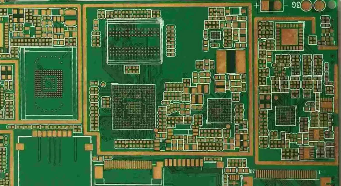
Component spacing has two purposes: allowing the convection heat to reach each joint, and allowing rework without disturbing neighboring parts. On a power board these distances are larger than on a standard assembly because the parts are physically bigger and their thermal mass is greater.
Large parts should be separated from each other and from small parts by at least 1 mm, and parts in an 0805 body size or smaller need at least 0.3 mm between them. The spacings are measured across the outermost dimensions of the parts, not between their pads, since it is the body that shades the convection flow. Where a design cannot meet these distances, the placement should be rearranged rather than accepted, because cold joints on a power board are both a functional and a safety concern.
Heavy components belong on the side that is reflowed only once, and they should not be placed shoulder to shoulder, since two adjacent heavy parts create a thermal shadow that neither the reflow profile nor the rework process can resolve efficiently.
Pad and Land Design
Pad design on a power board has to satisfy two competing requirements: enough copper to conduct heat away from the joint, and enough thermal isolation that the joint reaches soldering temperature. Thermal relief is therefore a design variable rather than a default, and the number and width of the spokes should be chosen to balance the two.
Two specific constraints apply to surface-mount pads. Vias placed directly in a solder pad will wick solder away from the joint during reflow unless they are filled and capped, so vias belong adjacent to the pad rather than inside it for a conventional assembly. Similarly, an open hole next to a pad will draw solder away from the joint, which is why the land pattern for each device should match the package recommendation and avoid features that compete for solder.
The land pattern also has to match the actual package. On a power assembly, a footprint taken from a generic library rather than the device datasheet is a common cause of a joint that looks acceptable and fails under thermal cycling, because the pad is either too small to form a proper fillet or too large to allow one to form at all.
Panel and Handling Requirements
Power boards are handled by the same conveyor and clamping systems as any other assembly, so the process edge must be intact. A notch or a gap in the conveyor edge will cause the board to jam, and the resulting mechanical stress can damage both the panel and the machine.
The panel array should leave an uninterrupted strip along both conveyor edges, with no components within the area reserved for tooling. Where the board is heavy because of large copper areas or large components, extra support may be needed during reflow, and that requirement should be identified before the panel is tooled.
Double-Side Process Sequence
Where both sides carry surface-mount components, the standard sequence is to print paste and place the parts on side A, reflow, invert the panel, print paste and place on side B, and reflow again. The sequence is chosen so that the side with the heavier components is reflowed first or last depending on the thermal and mechanical risk, and the decision must be consistent with the component temperature limits.
Where the assembly also includes through-hole parts, they are normally inserted after the surface-mount reflow and soldered by wave or selective soldering. On a power board, the through-hole content is often significant, so a pallet is usually required to protect the reflowed side and to support the weight of the assembly through the wave. Designing the panel with that fixture in mind avoids a late change to the array.
Inspection and Test
Inspection on a power assembly should include a check of every joint for adequate solder volume, with particular attention to the joints that carry current. Automated optical inspection covers the visible joints, and X-ray inspection is needed wherever a package hides its terminations. The electrical test should verify the insulation between high-voltage nets and ground, not only the continuity of the intended connections.
Where a design has a thermally driven failure mode, the check should be performed after a thermal cycle rather than before, since a marginally formed joint can measure correctly at room temperature and fail after the assembly has been through a temperature excursion. Related layout and assembly rules are covered in placement order and pad positioning and in SMT component shift causes, and the current-carrying requirements that drive the copper design are covered in trace width and current calculation.
FAQ
Why does a power board need larger component spacing than a standard board? Because the parts are physically larger and have more thermal mass, so they shade each other from the convection heat in the oven. A joint that never reaches temperature forms incompletely and may pass inspection while being mechanically weak.
Can vias be placed in the pads of a power device? Only if they are filled and capped. An open via in a pad wicks solder through the board during reflow, leaving a starved joint. If the via cannot be filled, it should be moved off the pad and connected with a short trace.
What should be verified before the first power board build? The components’ thermal ratings against the reflow profile, the spacing between large and small parts, the land patterns against the device datasheets, the integrity of the conveyor edges, and whether a pallet is required. Confirming these before tooling avoids most first-build failures.