Rapid PCB Prototyping From Design to Finished Board
Rapid pcb prototyping is less a manufacturing service than a development method. The board itself is not what makes a prototype fast; what makes it fast is the loop of design, build, test and revise being short enough that a designer can learn something new every week. Reducing the fabrication time from three weeks to three days changes how much of the design can be validated before the product is committed to tooling.
What Rapid Prototyping Is For
A prototype is a physical argument in support of a design decision. It exists to answer a question: does this regulator stay in regulation under load, does this interface close timing, does this enclosure fit around the tallest component. Rapid prototyping shortens the time between asking the question and receiving the answer, which is why its value is measured in iteration cycles rather than in units delivered.
The benefits follow from that. Development time falls because problems surface during design rather than during production qualification. Cost falls because the expensive changes happen while the artwork is still soft. Quality improves because the board that reaches production has already survived the tests that would otherwise have found its faults at volume.
Design Stage: Schematic and Layout
The schematic is where component choice, supply architecture and power dissipation are settled. Net classes are defined here as well, because the constraints that govern trace width, impedance and length matching have to exist before layout starts, not after. Assigning them later means reworking routing that was already correct for the wrong rules.
Layout then places and routes the board. Placement determines thermal behaviour, connector accessibility and the return path for every critical net. Routing then follows, and the objective is to keep signal paths short, keep return currents under their own traces, and leave the design in a state that a design rule check can pass without hand waivers.

Design Verification Before Fabrication
Three checks are performed before the artwork is released. A design rule check verifies that the layout obeys the fabricator capability, including minimum trace width and spacing, annular ring and drill size. An electrical rule check verifies the connectivity, catching nets that were intended to be joined but are not, and nets that were never meant to touch.
Simulation comes next for anything that cannot be checked geometrically: signal integrity on the high speed nets, power integrity across the supply impedance target, thermal behaviour near the dissipating components. Running these checks costs hours; discovering the same problem after fabrication costs a new set of boards and a week of schedule, which is the whole reason rapid prototyping exists.
Fabrication Stage: Getting Boards Quickly
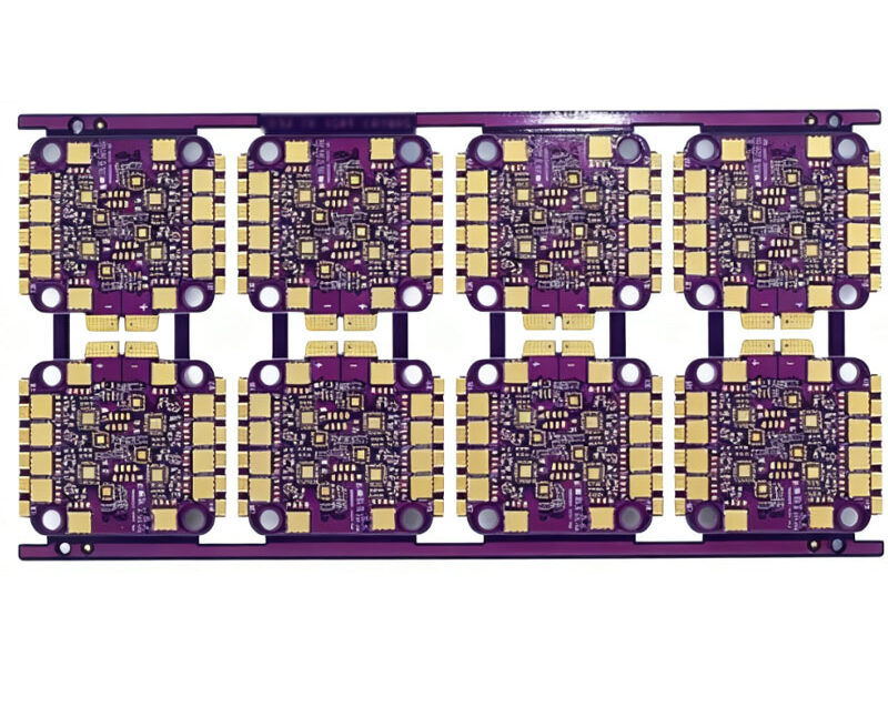
Fast turnaround fabrication relies on the same process steps as ordinary production, run with tighter queue discipline. Laser direct imaging removes the phototool step and allows a design to enter the line immediately. Mechanical drilling follows, with the drill programme generated automatically from the design data, and automated plating and etching lines hold the process windows that make short runs repeatable.
The result is that a small quantity of boards can be delivered in days rather than weeks, including multilayer designs. What the designer must provide is unambiguous data: a complete fabrication drawing, a defined stackup with layer thicknesses, and a surface finish specified by name, because an incomplete package is the most common reason a quick turn order stalls.

Assembly and Bring-Up
Once the bare boards arrive, components have to be placed and reflowed. Small prototypes are often assembled by hand or on a bench machine, which is acceptable for coarse packages but unreliable for fine pitch. Where the design includes 0402 passives or area array packages, sending the boards to a proper assembly line with a stencil and a reflow profile produces a much more meaningful test result.
Bring-up begins with the supply. Check each rail against its expected voltage before installing the expensive parts, then confirm the clock, then the reset sequence. Working in that order turns a board that does not boot into a short list of candidate causes rather than a long one, and it makes the difference between a prototype that informs a design decision and one that merely consumes a week.
Sourcing Components for a Prototype
Component availability decides the prototype schedule more often than fabrication does. A single part on extended lead time can delay a build by weeks even when the board is ready in days, so availability should be checked while the schematic is still being drawn. Designing around parts that are actually in stock is one of the cheapest schedule savings available.
Where the exact part is not available, a functional equivalent can be used for the prototype as long as the difference is recorded and the electrical behaviour is comparable. Substituting a different package, a different tolerance class or a different temperature grade changes the test result, and an unrecorded substitution turns a successful prototype into a misleading one. Consignment stock, kitting and a written alternates list all reduce the risk, and the assembly side of the same decision is covered in PCBA development process.
Test, Debug and the Next Iteration
Functional testing verifies that each block does what the specification says: the supply holds under load, the interface transfers data without errors, the output stage delivers its rated signal into its rated load. Performance testing then characterises the board across temperature, supply voltage and load, which is where marginal designs reveal themselves.
Every defect found should produce a written change, even when the fix seems obvious. A list of changes turns the next prototype into a controlled experiment rather than a set of edits, and it prevents the same fault from being reintroduced later. Failure analysis on the returned boards is what makes the second iteration faster than the first, and the DFM rules that keep it manufacturable are covered in design guidelines for manufacturability.
Iteration Discipline and Schedule
The number of iterations is a design decision, not an accident. Planning three cycles where two would suffice wastes money; planning one where three are needed wastes the schedule later. A useful discipline is to define in advance what each cycle must prove, and to release the board as soon as that question can be answered rather than waiting for the whole design to be perfect.
Schedule is dominated by the slowest item in the chain, which is usually a long lead time component rather than the board itself. Checking availability before layout is finished lets the design adapt, and ordering the bare board early while the parts list is still being confirmed is often worth more than any negotiation on fabrication price points.
FAQ
How fast can a first prototype realistically be built? With complete data, a two or four layer board can be fabricated in a few days and assembled in a few more. The variable is not the process but the completeness of the fabrication and assembly package.
Should the first prototype be assembled in house? Only if the packages are coarse and the quantity is one or two. Hand assembly of fine pitch parts introduces defects that are indistinguishable from design faults, which makes the test result misleading.
Do prototype boards need the same finish as production? They should use a finish the assembly process can handle, and preferably the same finish as production, since solderability and wetting behaviour differ between an organic preservative and a nickel gold surface, as described in multilayer prototype requirements.