Reflow Profile for Boards With Mixed Thermal Mass
A board with a heavy connector at one end and a fine pitch package at the other cannot reach the same temperature everywhere at the same time. The single profile that suits both is a compromise, and understanding the compromise is what makes the profile design deliberate.
Why Thermal Mass Varies
The temperature of a point on the board during reflow depends on the heat arriving from the oven and on the heat conducted away into the surrounding copper and into the component bodies.
A small component on a short trace heats quickly, while a large connector with a metal shell and a wide pad heats slowly because the metal conducts heat away faster than the air supplies it.
The difference is not small. A board can easily show a spread of twenty to thirty degrees between the hottest and coldest points at the moment the solder melts. The profile must ensure that the coldest point still reaches the required temperature while the hottest point does not exceed the limit of the most sensitive component.
Thermocouple Placement
The measurement is made with thermocouples attached to the board, and the choice of attachment affects the reading. A thermocouple held by tape measures the air near the joint, while one bonded with a high temperature adhesive or attached through a hole measures the board itself.
The standard practice is to attach the thermocouple to a pad or a joint using a small amount of adhesive, with the bead in contact and the leads running along the board so that they conduct heat away predictably.
The number and location of the probes decide how much of the board is characterised. The minimum useful set is the coldest point, the hottest point and one point in the middle, with additional probes where a component has a temperature limit.

The Four Zones and What Each Does
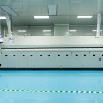
The preheat zone brings the assembly up to a temperature at which the flux activates and the volatiles begin to leave. The soak zone holds that temperature long enough for the whole board to reach a similar state, which is what reduces the spread.
The reflow zone raises the temperature above the liquidus of the alloy, and the time above liquidus determines how much intermetallic growth occurs and how well the solder wets.
The cooling zone controls the grain structure of the joint. Cooling too slowly produces a coarse structure and too quickly can produce thermal shock. The rate is part of the specification rather than a consequence.

Finding the Window
The window is bounded below by the coldest point reaching the required temperature for long enough and above by the hottest point staying below the limit of the most sensitive part.
Where the two bounds cross, the board cannot be soldered with a single profile and the options are to redesign the thermal mass distribution, to change the alloy to one with a lower melting point, or to use two passes with different profiles.
Reducing the difference in thermal mass is usually the best answer. Adding copper to the light area or thermal relief to the heavy area brings the two ends closer, and it is a design change that removes the constraint permanently.
Alloy Choice and the Window
A lead free alloy melts at a higher temperature than a tin lead alloy, which narrows the window between the required reflow temperature and the limit of the components. This is why a board that profiles easily with tin lead can be marginal with lead free.
Where the components are limited to a lower temperature, a lower melting point lead free alloy such as one containing bismuth can be used, at the cost of different mechanical properties and a narrower process window elsewhere.
The alloy should be chosen before the profile is developed, because the profile follows from the alloy and not the reverse. Our solderability notes describe how the alloy and the finish interact.
Verification and Records
A profile is verified by measuring the actual board, not by reading the oven’s own thermocouples. The oven display shows the air temperature at the sensor, which is not the temperature of the board.
The verification should be repeated whenever anything changes: the oven, the board revision, the component mix, the paste or the conveyor speed. A profile recorded for one configuration is not evidence for another.
The recorded profile should include the probe locations, because the numbers are meaningless without knowing where they came from. Our quality notes describe how the profile record is filed with the lot.
Diagnosing a Profile Problem
An insufficient solder defect at one end of the board and good joints at the other suggests a thermal mass gradient. The same defect scattered randomly suggests a paste or stencil problem rather than a profile one.
A component with a cracked body after reflow suggests a heating or cooling rate that exceeded what the body could tolerate, which points at the ramp rather than at the peak. Our solder defects notes describe the appearance of each failure.
Voids that increase without any change in the paste point at the soak, since a shorter soak leaves more volatiles in the joint when the solder solidifies.
Working With the Assembly House
The profile is developed by the assembly house, and the designer’s contribution is the information that constrains it: the temperature limits of the parts, the thermal mass distribution and the requirement for any particular joint.
Where a component has an unusual limit, that limit should be given explicitly rather than left in a data sheet that nobody opens. Our thermal design notes describe how the board’s copper distribution is planned in the first place, which is the upstream decision that determines how hard the profile is to develop.
Additional Considerations for This Build
Practical attention to reflow profile pays for itself here, because it decides whether the finished board behaves as the drawing intended. Where the requirement is not stated on the fabrication drawing or in the assembly notes, the shop has to assume a default, and that default is rarely the value the design was simulated with. Stating reflow profile explicitly, together with the tolerance that applies, removes the assumption and keeps the result predictable from batch to batch.
Process Control and Verification
On a design of this kind, thermal mass is the item that decides how the rest of the board is arranged. Keeping a sample from the panel turns a dispute into a measurement, because the same coupon can be re-examined by both parties without rebuilding the batch. Reviewing the design before the data is released is cheaper than correcting it after the panel is in the tank, because every step downstream inherits the decision made at the front end.
Documenting the assumption is part of the design work, and a short note on the drawing prevents a question that would otherwise arrive a day later and cost a day of schedule.
FAQ
How many thermocouples are enough? Enough to characterise the extremes and any point with a constraint. Three is a workable minimum on a simple board and six or more is normal on a mixed assembly.
Can a profile be reused from a similar product? It can be used as a starting point, and it must be verified on the new board before production.
What does gopcb provide for reflow profiling? We provide profile development with documented probe locations, measurement of the spread across the board, verification records repeated after any change, and alloy selection guidance where the window is narrow. Where the spread cannot be closed by profiling, we propose the design change that closes it.