What Is a Rigid-Flex PCB?
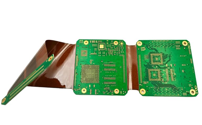
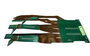
A Rigid-Flex PCB is a printed circuit board that combines rigid and flexible circuit technologies into a single integrated structure. By combining the mechanical stability of a rigid board with the flexibility of a flexible circuit, a Rigid-Flex Circuit Board can provide reliable electrical connections while fitting into compact, irregular, or three-dimensional product structures.
Unlike conventional rigid and flexible PCBs that are manufactured separately and connected with cables or connectors, a rigid-flex design integrates the rigid and flexible sections into one PCB assembly. This can reduce the number of interconnections, simplify assembly, save space, and improve overall system reliability.
The flexible section is commonly constructed using polyimide-based materials with copper conductors, while the rigid section may use FR-4 or other suitable rigid laminates. These sections are integrated through carefully controlled bonding and lamination processes. Depending on the design, adhesive systems and prepreg materials may be used to achieve the required mechanical and electrical performance.
The flexible area allows the circuit to bend or fold within specified mechanical limits, while the rigid area provides stable mounting locations for components and connectors. This combination makes Rigid-Flex PCB technology particularly valuable for applications where space, weight, reliability, and mechanical integration are important.
What Are the Advantages of Rigid-Flex PCBs?
Both conventional rigid PCBs and flexible PCBs have their own advantages and limitations. A rigid PCB provides excellent mechanical strength but cannot easily adapt to complex three-dimensional structures. A Flexible PCB, on the other hand, can bend and fold but generally provides less mechanical support for components.
A Rigid-Flex Circuit Board combines these characteristics to create a more integrated solution.
Reduced Weight
A rigid-flex design can eliminate many conventional cables, connectors, and wire harnesses. By integrating these interconnections directly into the PCB structure, the total number of components and mechanical parts can be reduced.
This weight reduction is particularly beneficial for portable electronics, aerospace equipment, medical devices, automotive systems, and other applications where size and weight are important design considerations.
Improved Flexibility and Three-Dimensional Integration
One of the most significant benefits of a Rigid-Flex PCB is its ability to conform to complex product geometries.
The flexible sections can be bent or folded within the specified bend radius, allowing designers to route circuits through narrow spaces and around mechanical structures. This can provide greater freedom when designing compact products and three-dimensional electronic assemblies.
However, flexibility must be designed according to the construction of the flexible section. Bend radius, copper type, number of layers, coverlay structure, material selection, and dynamic or static bending requirements all affect the achievable flexibility.
Smaller Product Size
Traditional PCB assemblies often require connectors, cables, and additional mechanical space to connect separate circuit boards. A rigid-flex structure can integrate these connections directly into a single assembly.
As a result, designers can reduce connector count, simplify cable routing, and optimize the internal layout of the product. This is particularly useful for miniaturized electronic devices and products with limited internal space.
Higher Interconnection Reliability
Every connector, cable, or soldered connection introduces another potential failure point. By reducing the number of external interconnections, a Rigid-Flex Circuit Board can improve overall system reliability.
The flexible section can also absorb certain mechanical stresses caused by vibration, movement, or thermal expansion. When properly designed and manufactured, rigid-flex technology can provide stable electrical performance under demanding operating conditions.
Better Mechanical Integration
The rigid sections provide stable areas for mounting components, connectors, shields, and mechanical fixtures, while the flexible sections allow the circuit to move or conform to the product structure.
This makes rigid-flex technology particularly suitable for products where the PCB must serve both an electrical and mechanical integration function.
Rigid-Flex PCB Applications
The combination of rigidity, flexibility, compactness, and reliability makes Rigid-Flex Applications increasingly common across multiple industries.
Medical Electronics
Medical devices often require compact electronic assemblies with high reliability. Implantable and wearable medical products can benefit from the small size and reduced interconnection count of rigid-flex designs.
Applications may include medical monitoring equipment, portable diagnostic devices, surgical instruments, wearable medical electronics, and selected implantable electronic systems.
Aerospace and Defense
Weight reduction and reliability are critical considerations in aerospace and defense electronics. A rigid-flex solution can replace multiple cables and connectors while reducing assembly weight and improving packaging efficiency.
Rigid-flex boards may be used in avionics, communication systems, navigation equipment, control systems, and other specialized aerospace and defense electronics.
Industrial Equipment
Industrial equipment often contains motors, sensors, control modules, displays, and moving mechanisms. A rigid-flex structure can provide reliable electrical connections while accommodating movement or limited installation space.
Potential applications include industrial control systems, instrumentation, robotic equipment, motor control systems, and automated machinery.
Consumer Electronics
Consumer electronics increasingly require smaller and thinner internal structures. Rigid-Flex PCB technology can help manufacturers optimize internal space while reducing cable assemblies.
Common applications include wearable devices, smartwatches, wireless earphones, cameras, smartphones, tablets, gaming equipment, and other compact electronic products.
Automotive Electronics
Modern vehicles contain increasingly sophisticated electronic systems installed in areas with limited space and significant vibration and temperature variation.
Rigid-flex solutions can be used in selected automotive control systems, displays, sensors, infotainment equipment, lighting systems, and other electronic modules where compact packaging and reliable interconnection are required.
How Is a Rigid-Flex PCB Manufactured?
The Rigid-Flex PCB Manufacturing process is more complex than the production of a conventional rigid PCB because it combines different materials and mechanical requirements within the same board.
The manufacturing process must account for material compatibility, layer alignment, flexible-area protection, copper reliability, bending requirements, and lamination behavior.
1. Engineering Design and Stack-Up Development
The Rigid-Flex PCB Manufacturing process begins with engineering review and PCB design.
Designers must define the rigid and flexible regions, layer count, material stack-up, copper thickness, bend areas, bend radius, via structures, component locations, and mechanical dimensions.
The stack-up should be designed according to the intended electrical and mechanical requirements. Flexible areas normally require special consideration because excessive copper, sharp corners, or inappropriate layer transitions can reduce bending reliability.
Design for Manufacturing (DFM) analysis should also be performed before production to identify potential manufacturing risks.
2. Material Preparation
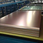
The materials used in a Rigid-Flex Circuit Board typically include flexible copper-clad laminate, polyimide film, coverlay, rigid laminate such as FR-4, prepreg, copper foil, and bonding materials.
Material selection depends on the application’s temperature range, flexibility requirements, electrical characteristics, mechanical stress, and reliability requirements.
For high-reliability applications, materials should be selected based on their thermal expansion characteristics, dimensional stability, dielectric properties, and resistance to environmental stress.
3. Circuit Imaging and Pattern Formation
Circuit patterns are created on the copper layers using imaging and etching processes.
Photoresist is applied to the copper surface and exposed according to the designed circuit pattern. After development, unwanted copper is removed through controlled chemical etching.
For fine-line rigid-flex designs, imaging accuracy and etching control are especially important because dimensional variations can affect both electrical performance and mechanical reliability.
4. Drilling and Laser Via Formation
Mechanical drilling and laser drilling may be used to create through-holes, blind vias, microvias, and other required openings.
The appropriate drilling technology depends on the board construction, hole diameter, layer structure, and design density.
During drilling, manufacturers must carefully control parameters to minimize burrs, delamination, resin damage, and other defects. Flexible materials require additional process considerations because excessive mechanical stress can damage the flexible layers.
5. Copper Plating
After drilling, conductive material must be deposited onto the hole walls to establish electrical connections between PCB layers.
Chemical copper deposition is typically followed by electroplating to build the required copper thickness. Plating quality is particularly important for rigid-flex designs because plated through-holes and vias may experience mechanical stress during bending or thermal cycling.
Proper control of copper thickness, adhesion, and plating uniformity contributes significantly to long-term reliability.
6. Etching
The exposed copper is selectively removed to form the required circuit traces and conductive features.
Etching parameters must be carefully controlled to maintain consistent trace width and spacing. Over-etching can reduce conductor width, while under-etching can cause unwanted copper residues or shorts.
For high-density Rigid-Flex PCB designs, precise process control is essential.
7. Coverlay and Solder Mask Application
The flexible section commonly uses a polyimide coverlay to protect the copper conductors and provide electrical insulation. Coverlay is different from conventional solder mask and is an important part of flexible circuit construction.
The rigid section may use liquid photoimageable solder mask or another appropriate protective coating.
The transition between rigid and flexible areas must be carefully designed and processed to prevent mechanical stress concentration and material damage.
8. Lamination and Bonding
Lamination is one of the most critical stages in Rigid-Flex PCB Manufacturing.
The rigid and flexible structures are combined using controlled heat and pressure. Prepreg, adhesive films, and other bonding materials may be used according to the stack-up design.
Temperature, pressure, heating rate, curing conditions, and material flow must be controlled precisely. Poor lamination can result in voids, delamination, wrinkles, dimensional instability, or other reliability problems.
9. Surface Finish
A suitable Surface Finish is applied to exposed copper pads to prevent oxidation and provide reliable solderability.
Common surface finishes include ENIG, HASL, OSP, immersion silver, and immersion tin. The appropriate finish depends on the component package, assembly process, environmental requirements, storage conditions, and expected product lifetime.
For fine-pitch components and high-density rigid-flex designs, ENIG is often considered because of its relatively flat surface and good solderability.
10. Silkscreen and Identification
Silkscreen or other marking processes can be used to add component reference designators, polarity indicators, logos, manufacturing information, and traceability markings.
Markings should be positioned carefully so that they do not interfere with solder pads, flexible bending areas, or other critical features.
11. Electrical Testing and Final Inspection
Electrical testing is performed near the end of the Rigid-Flex PCB Manufacturing process to verify circuit continuity and isolation.
Depending on product requirements, manufacturers may use flying probe testing, fixture-based testing, automated optical inspection (AOI), dimensional inspection, and other quality-control methods.
Rigid-flex products may also require additional mechanical or reliability evaluations, especially when the flexible section is designed for repeated movement or dynamic bending.
Important Design Considerations for Rigid-Flex PCBs
Successful rigid-flex design requires more than simply combining rigid and flexible PCB materials. Designers should consider mechanical, electrical, thermal, and manufacturing requirements from the beginning of the project.
Bend Radius
The bend radius is one of the most important parameters for a Rigid-Flex PCB. Bending the flexible section beyond its recommended radius can damage copper conductors or other materials.
The appropriate bend radius depends on the flexible material, layer count, copper construction, and whether the application requires static folding or repeated dynamic bending.
Copper Design
Copper traces in flexible regions should be designed to withstand mechanical stress. Trace routing, conductor geometry, copper type, and layer transitions can all influence flexing reliability.
Avoiding unnecessary sharp corners and minimizing mechanical stress concentrations can help improve the service life of the flexible section.
Transition Area Design
The transition between rigid and flexible regions is particularly important. Sudden changes in thickness or stiffness can concentrate mechanical stress.
A carefully designed transition structure helps distribute stress and reduces the risk of cracking or delamination.
Material Compatibility
Rigid and flexible materials have different mechanical and thermal characteristics. Material selection should therefore consider thermal expansion, moisture absorption, dielectric performance, adhesive compatibility, and long-term reliability.
Manufacturing Capability
Because rigid-flex fabrication is more complex than conventional PCB production, the manufacturer’s capabilities should be evaluated before finalizing the design.
Important factors include minimum trace width and spacing, layer count, flexible-layer construction, bend radius capability, drilling accuracy, plating performance, lamination technology, inspection capability, and reliability testing.
Why Choose Kingda for Rigid-Flex PCB Manufacturing?
Choosing the right Rigid-Flex PCB Manufacturing partner is essential for projects that require complex structures, tight mechanical constraints, and high reliability.
Kingda provides customized rigid-flex PCB solutions for different industries and application requirements. Our engineering and manufacturing teams can work with customers throughout the design and production process.
Professional Engineering Support
Rigid-flex designs require close cooperation between PCB designers and manufacturers. Kingda can support engineering review, stack-up optimization, DFM analysis, material selection, bend-area evaluation, and manufacturing process planning.
Early engineering involvement can help identify potential production problems before manufacturing begins.
Comprehensive Manufacturing Capabilities
Kingda supports different rigid-flex structures, layer configurations, materials, copper thicknesses, via technologies, and surface finishes.
Manufacturing solutions can be customized according to the electrical, mechanical, thermal, and reliability requirements of each project.
Strict Quality Control
Quality control is integrated throughout the Rigid-Flex PCB Manufacturing process, including incoming material inspection, imaging, drilling, plating, etching, lamination, surface treatment, electrical testing, and final inspection.
Process monitoring and inspection help ensure that finished boards meet the required specifications and reliability targets.
Competitive Manufacturing Solutions
Kingda works with customers to balance technical requirements, production volume, material selection, manufacturing complexity, and cost.
Through appropriate material and process selection, we can help customers develop practical rigid-flex PCB solutions while maintaining the required performance.
Reliable Delivery and Customer Support
From prototype development to volume production, Kingda emphasizes communication, engineering coordination, and production planning.
Our technical team works closely with customers to address manufacturing questions and optimize production according to project requirements.
Conclusion
A Rigid-Flex PCB combines the mechanical stability of a rigid board with the flexibility of a flexible circuit, providing an effective solution for compact, lightweight, and highly integrated electronic products.
Compared with conventional PCB assemblies connected by cables and connectors, a Rigid-Flex Circuit Board can reduce interconnections, save space, lower weight, and improve mechanical integration. These advantages make rigid-flex technology valuable in medical electronics, aerospace, automotive systems, industrial equipment, consumer electronics, and other advanced applications.
However, successful rigid-flex production requires careful attention to material selection, stack-up design, bend radius, copper routing, transition areas, lamination, plating, and reliability testing. Working with an experienced Rigid-Flex PCB Manufacturing partner from the early design stage can significantly reduce manufacturing risks and improve product reliability.
With professional engineering support and customized manufacturing capabilities, Kingda can provide reliable rigid-flex PCB solutions for prototypes, small-batch production, and volume manufacturing.