Set Top Box Mainboard Design With GPS Positioning
A set top box that reports its own position combines a video platform with a radio receiver, and the two have to share one board without interfering. Set top box mainboard design in this case is mostly a question of where the receiver and its antenna are allowed to live.
What the Mainboard Contains
The board carries the media processor, the memory and storage, the video and audio outputs, the network interfaces and the positioning receiver. It also carries the power conversion for all of them.
Each block has a different requirement, and the positioning receiver is the one that constrains the arrangement of the others. Its signal is weak and its frequency is high, so it is treated as the sensitive block on the floor plan.
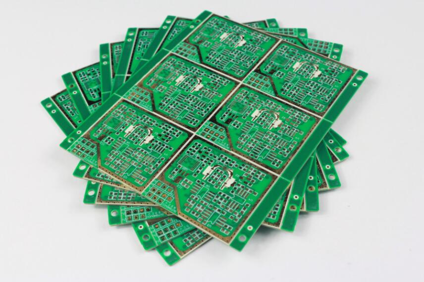
<img src="https://www.gopcba.com/wp-content/uploads/2026/09/65.webp" alt="Set top box mainboard with gps module and connectors” />
The Positioning Module
A positioning module integrates the radio, the baseband and the firmware in one package, and it presents a serial interface and a pulse per second output. Using a module removes most of the radio design work.
The module still needs a clean supply, a good ground and a correctly placed antenna, and those three items are where most of the problems occur. A module placed against a switching converter will take longer to obtain a fix.
Antenna Placement
The antenna has to see the sky, which in a box installed indoors usually means it is placed at the edge of the board or brought out on a short cable. A metal enclosure shields the antenna and a coated plastic case does not.
Keep the antenna away from the switching supplies, the display interface and any large heatsink, and provide a ground plane of the size the antenna data sheet assumes. An antenna without its reference plane behaves as a different antenna.
Radio Frequency Front End
From the antenna to the module the signal passes through a filter, a matching network and a short transmission line. That path is designed as a controlled impedance line, with the impedance defined by the module rather than by the board.
Keep the path short, keep it straight, and keep it on one layer where possible. Every via in a radio frequency line adds an impedance discontinuity, and the loss shows up as a longer time to first fix.

Power Supply Design
The mainboard needs several rails: a main rail for the processor, a lower rail for the memory and a quiet rail for the radio and its analogue stages. Each is produced by its own converter with its own filtering.
The power supply is also the main source of interference on the board. Keep the switching loop small, keep the inductors away from the antenna, and filter the rail that feeds the receiver before it reaches the module.
Video and Audio Outputs
Video is usually available as high definition multimedia or as a composite output, and the interface chosen decides the connector and the routing. The high speed link is routed as a matched group with a continuous reference.
Audio may be analogue or embedded in the video stream. Where an analogue output is provided, its ground reference and its filter are kept away from the digital return currents that run through the same area.
Network and Storage
Ethernet, Wi Fi and sometimes a mobile module provide the connectivity. Each has its own antenna or cable requirement, and the layout has to leave room for them without crowding the positioning antenna.
Storage is often a card socket or an embedded flash device. The card socket is a mechanical interface as well as an electrical one, so its position follows from how the user can reach it.
Interfaces for the Operator
The remote control receiver, the front panel indicator and the button are all board level interfaces. Their positions are decided by the enclosure, and their wiring has to avoid the radio section.
An infrared receiver needs a window in the case and a clear line of sight. Placing it behind a coated plastic panel that blocks infrared is a mistake that is discovered only when the product is assembled.
Grounding and Shielding
A single continuous ground plane with the radio section placed over an undisturbed area is the usual approach. Where the board is dense, a shield can be added over the radio path and bonded to ground at many points.
Shield cans are most effective when their ground connections are short and numerous. A can that is soldered at four corners and left open elsewhere still allows the field to leak around its edges.
Thermal Considerations
The processor and the power converters both dissipate heat, and a sealed box has only the case to conduct it into. Copper area and a defined contact with the housing are the two levers.
Temperature also affects the receiver. A crystal that is held well above the ambient at which it was calibrated drifts, and the frequency error costs acquisition time.
Firmware and Position Data
The module delivers position, time and status over a serial link, and the application has to handle the periods when no fix is available. Caches and previous positions are used to keep the service usable indoors.
The pulse per second output is a precise timing reference and is worth routing as a short, protected signal. It is often used to discipline a clock in the processor as well as to timestamp data.
Regulatory Considerations
A product with a radio transmitter is subject to certification, and the same applies to a receiver that is marketed as a positioning device. The tests cover emissions and immunity, and the antenna arrangement is part of what is tested.
The board layout therefore cannot be changed freely after certification. Antenna position, cable routing and the shield arrangement are the items that most often invalidate a test result when they are altered.
Mechanical Integration
The mainboard outline, the connector cut outs and the mounting points come from the enclosure. The electrical design then has to work within that shape, including the height limits above and below the board.
Standard practice for those constraints is described in our notes on board outline and mounting, and the same rules apply to the power section covered in our converter layout guidance.
Testing
Validation covers the video path, the network interfaces, the power consumption in each mode and the acquisition time of the receiver. The last of these is measured outdoors or with a simulator, not next to a window.
Sensitivity is worth measuring with the display active, because that is the condition the product works in. A receiver that is marginal with the display running is marginal in the field.
Design Checklist
Before release, confirm the antenna clearance, the ground plane under the antenna, the supply filtering for the module and the separation from the switching stages. Check the impedance of the radio path on the coupon if the line is long.
Then confirm the mechanical fit and the connector access. A board that is electrically correct but cannot be assembled has not been designed, and the checks used here follow the design quality criteria.
FAQ
Does a GPS receiver need its own ground plane? It needs a reference plane of the size the antenna expects, and that plane should be free of other high speed routing. The specification belongs to the antenna rather than to the module.
Why does the receiver take longer to fix indoors? Because the signals are attenuated by the building. A better antenna position and a lower noise floor near the module usually improve the result more than a different module would.
Can the receiver share a rail with the processor? It can operate, but the acquisition time and the noise figure suffer. A separate filtered rail is the usual choice for a product that has to position itself reliably.