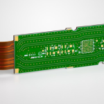
Six Layer Stackup for an Automotive Infotainment Board
A centre console board connects a display, a camera, a radio, a touch panel and the vehicle network, all inside a dashboard that bakes in the sun and hums with electrical noise. A six layer stackup has become the standard answer for that class of product because it provides two inner planes and two routing layers while keeping the cost below an eight layer build.
Why Six Layers
A four layer board gives two routing layers and two planes, which is enough for a simple controller but tight for a board that carries a display interface, a camera link and a network, and once a plane has to be split to carry both ground and power the reference for the high speed lines is no longer clean. The routing fills quickly, and the plane that is left is forced to serve as both a reference and a power distribution layer.
Six layers allow a dedicated ground reference next to each signal layer, which keeps the return paths short and gives the high speed interfaces a stable reference. That arrangement is the main electrical benefit, and it is what makes the layer stackup from one to eight layers a useful reference for the trade between layer count and cost.
A Typical Layer Assignment
A common arrangement places the high speed signals on the outer layers, ground on layers two and five, and power and slow signals on the inner layers. Each signal layer then has an adjacent plane, which controls the impedance and provides the return path.
An alternative places the high speed signals on inner layers four and five between the two ground planes, which gives better shielding against radiation at the cost of burying the traces and making the routing harder. The choice depends on whether the dominant concern is emission or routability.
Display and Camera Interfaces
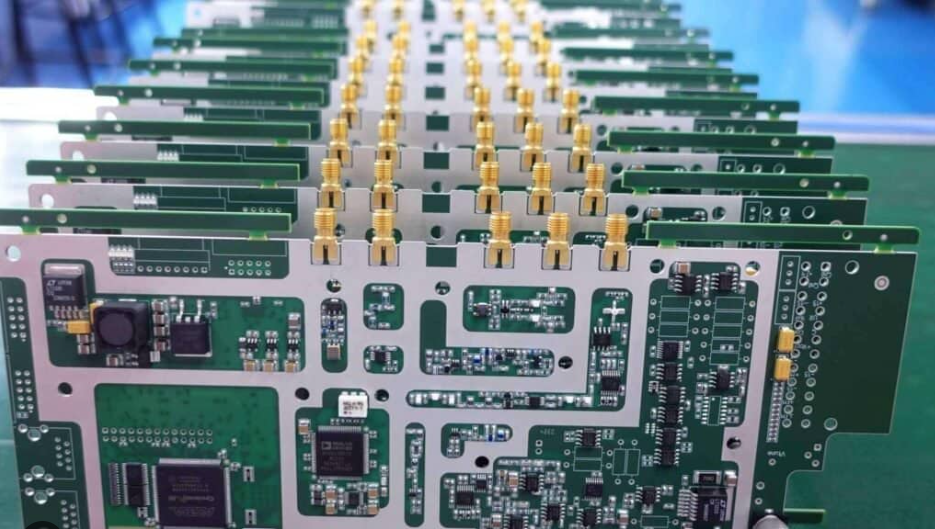
The display link carries several differential pairs at rates high enough to require impedance control and length matching, and the camera link is similar. Both are routed as groups, with the pairs matched to each other within a lane and the lanes matched where the protocol requires it.
Impedance control on these interfaces is specified as a tolerance with a coupon, and the reference plane must be continuous beneath the whole run. Layer changes are kept to a minimum and, where they occur, the return path travels with the signal through an adjacent ground via. The general techniques are described in the material on mixed signal PCB design guidelines.
Electromagnetic Compatibility in the Cabin
The cabin is an electrically noisy environment. The board has to tolerate interference from the alternator, the ignition system and the other modules on the network, and it must not radiate enough to disturb the radio or the vehicle receivers.
Filtering at every connector is the first measure, since the harness is the path by which interference enters and leaves. The second is the ground arrangement: a continuous reference with no plane splits under high speed lines, and connectors whose shields are bonded to it in a way that does not inject current into the signal ground. The board should also avoid long unshielded loops, which act as antennas at the frequencies involved.
Power Distribution and Noise
The board runs from the vehicle supply, which varies widely and carries transients. A wide input range regulator with protection at the connector handles that, and the local rails are generated by switching converters whose switching noise must not reach the display or the camera interface.
Separate returns for the switching converters and the sensitive interfaces, and a filtered supply to the display, are the practical measures. The power plane assignment should reflect that separation rather than presenting one large conductive area that couples the noise everywhere. Component placement follows the same separation, with the converters grouped on one side of the board and the interfaces on the other.
Thermal Management in a Dashboard
A dashboard in direct sun can reach very high temperatures, and the board generates its own heat from the processor and the display backlight driver. There is no fan, and the enclosure is usually closed, so the heat leaves by conduction into the housing.
Copper area under the processor, thermal vias into the ground plane, and a mounting arrangement that presses the board against a metal frame are the available tools. Electrolytic capacitors are the most temperature sensitive parts and should be placed away from the hottest area, and the thermal design should be verified with the board running at full brightness in an enclosure rather than on an open bench.
Materials and Reliability
A high glass transition laminate is normal for this application, because the assembly is lead free and the operating temperature is high. The material choice is a reliability decision as much as a process one, and the reasoning is the same as for any automotive board.
Thermal cycling between a cold winter morning and a hot dashboard is severe, and it fatigues the joints on large components. Ceramic capacitors need a compliant termination or a softer alloy, and heavy parts need mechanical support. The alloy and joint considerations are set out in the material on lead-free versus leaded solder, applied with the automotive temperature range in mind.
Mechanical and Connector Design
The board is mounted behind a display in a housing that also carries the connectors for the vehicle harness. Connector placement has to allow the harness to be routed without strain, and the retention has to survive the vibration of the vehicle.
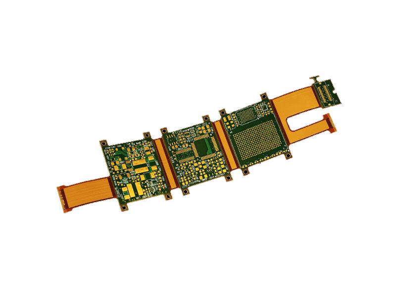
Through hole or mechanically retained connectors are preferable to parts held by solder joints alone, and the assembly should be supported near the connectors during insertion. Where the board carries a display connector that mates with a flexible cable, the alignment tolerance between the connector and the housing becomes part of the mechanical stack, and it should be analysed together with the outline and mounting tolerances rather than after the enclosure is tooled.
Test and Validation
Production test covers the electrical functions, and validation covers the environment: temperature cycling, high temperature storage, vibration, humidity with bias and the EMC tests that apply to the vehicle class.
The display interface deserves a specific test at temperature, because a marginal link may work at room temperature and fail when the driver is hot. Measuring the eye at the extremes, or at least checking for errors under load at both temperature limits, is what catches that class of fault before it reaches a customer, and it is far cheaper than a field fix on a part that has to be removed from a dashboard to be replaced.
FAQ
Is six layers enough for a modern infotainment board? For a single display and a camera interface, usually yes. Boards with multiple high speed links and a large processor often need eight, driven by the number of interfaces rather than by the components.
Should the high speed signals be on the outer layers? Outer layers are easier to route and to inspect, while inner layers between planes are better shielded. The choice follows from whether emission or routability is the harder constraint.
How is the board protected from the environment? A conformal coating is common where humidity or condensation is expected. The display connector and any pressure sensitive parts must be masked, and the coating must be specified by material and thickness.