




SMT Dispensing Machine Guide: Adhesive and Soldering
A SMT dispensing machine guide helps engineers choose the right equipment for adhesive, solder paste, and underfill applications. Dispensing is used when ordinary solder paste printing cannot support the component or when a part must stay in position before soldering. Automatic SMT lines commonly dispense chip adhesive, conductive adhesive, underfill, and masking material.
Some electronic components cannot be soldered safely with standard paste printing. Small devices, bottom-side parts, heat-sensitive components, and large components may require controlled material deposition before reflow or wave soldering.
This guide explains dispenser types, dispense head designs, and the main soldering methods used in SMT PCB assembly.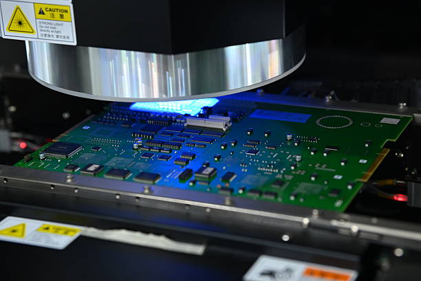
Why SMT Production Uses Dispensing
During SMT production, solder paste printing works well when all components can be placed onto wet paste and then reflowed. Some assemblies need a different method because their components are fragile, heavy, unusually shaped, or located on both sides of the board.
Adhesive dispensing is used to bond components before wave soldering. The adhesive holds each part in place while the board passes through the molten solder wave. This process supports small SMD components and helps prevent them from moving during soldering.
Dispensing is also used for underfill, which strengthens the connection between a chip and its substrate, and for conformal masking, which protects selected areas from coating. The dispensing process must deliver a controlled volume at an accurate position without creating tails, voids, or excess material.
The choice between printing and dispensing depends on the material, component layout, production volume, and required accuracy.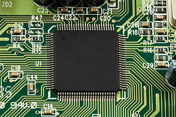
Manual and Automatic Dispensers
Manual dispensers are simple tools that let an operator control the amount of adhesive or paste applied to the board. They are practical for prototypes, low-volume production, rework, and applications where only a few dots are required.
Automatic dispensers move along the X, Y, and Z axes and apply material according to a program. They provide consistent dot size, placement, and cycle time for medium and high-volume production.
Automatic machines are usually programmed from a CAD or Gerber file. The operator defines the material, needle or jet settings, dispense height, speed, and volume for each dot or line.
For very large volumes, dispensing can be combined with screen printing or stencil printing to achieve high throughput while retaining flexibility for unusual components.
Dispenser Head Technology
The dispense head is the most important part of the machine. It controls the amount, shape, and position of the material. Most production heads use one of four technologies: time-pressure, auger screw pump, linear positive displacement, or jet pump.
Each head type has different strengths. The correct choice depends on the adhesive viscosity, dot size, material sensitivity, board warpage, and production speed.
A machine may use different heads for different products. Some systems allow the head to be changed when the process requires another method.
Time-Pressure Dispense Heads
Time-pressure dispensing heads use controlled pulses of compressed air to push material from a syringe or cartridge. The material flows through a needle and forms a dot when the air pressure is released.
The amount of material depends on the pressure, pulse time, needle diameter, material viscosity, and temperature. A longer pressure pulse generally pushes out a larger amount of material, while a shorter pulse creates a smaller dot.
Time-pressure systems are simple, inexpensive, and easy to maintain. They are often used for adhesives and pastes with consistent viscosity.
The main limitation is that output can change as the material level in the syringe drops. Viscosity changes and air bubbles in the cartridge can also affect dot size, so the process must be checked regularly.
Auger Screw Pump Heads
Auger screw pump heads use a rotating screw to move material through a needle or nozzle. The screw provides positive feeding and helps create a more consistent flow than a simple air pulse.
This type of head is flexible and can handle many kinds of SMT adhesives. It is less sensitive to air trapped in the material because the screw continuously moves the material toward the needle.
Auger systems can be sensitive to viscosity changes. If the material becomes thicker or thinner, the volume delivered by each rotation changes. The rotation speed also affects dispense consistency.
The machine should be calibrated for the material lot and checked at the beginning of each production run.
Linear Positive Displacement Heads
Linear positive displacement heads push a measured volume of material through the needle using a piston or rod. The output is defined by the piston stroke rather than by air pressure or material level.
This design produces very consistent dot size, especially at high speed. It can dispense larger dots and is often used when the amount of material must remain stable over a long production run.
The cleaning procedure is more complex because the piston and chamber contact the material. The head must be cleaned carefully when the adhesive changes or when production stops.
Linear displacement heads can be sensitive to air bubbles in the material. Air in the chamber compresses and reduces the volume of material delivered, so the material should be deaerated before use.
Jet Pump Dispense Heads
Jet dispensing heads do not need to touch the board. A small plunger accelerates the material and ejects it as a droplet toward the target. The jet can dispense very small dots quickly because the head does not move down and up for every dot.
Jet systems are not sensitive to board warpage or height differences. The head can dispense material from a fixed distance above the board, which is useful when components vary in height.
Large dots may require multiple jets or a slower cycle, and the nozzle requires careful cleaning. Jet heads also need a material formulation with the correct flow behavior so that clean droplets are formed.
Jet dispensing is popular for underfill, chip adhesive, and fine features that need high speed with accurate volume.
Wave Soldering Technology
Wave soldering is used for through-hole components and for boards that combine through-hole and SMT devices. Adhesive is applied to the SMT components first so they stay in place when the board passes over the molten solder wave.
The board is carried across the wave machine, preheated, and then exposed to a pumped wave of molten solder. The solder wets the exposed pads and component leads to create the connection.
Wave soldering can process both sides of a board in one pass. This helps reduce product size because small components can be mounted on the bottom side without an additional reflow cycle.
The limitation is that high-density SMT assemblies are difficult to solder by wave. Fine-pitch devices, very small pads, and large BGAs cannot always survive the solder wave or receive enough solder in the correct location.
Reflow Soldering Technology
Reflow soldering is the main method used in modern SMT production. Solder paste is printed onto the PCB pads through a stencil, components are placed onto the paste, and the board passes through a reflow oven.
In the oven, the solder paste is heated through several zones. Solvents evaporate, flux activates, and the solder particles melt and flow together. After cooling, the solder forms a solid connection between the pad and the component lead.
Reflow soldering is simple, fast, and repeatable for most SMT components. The process is controlled by a thermal profile that matches the solder alloy, board thickness, component mass, and paste type.
The stencil aperture and solder paste volume determine how much solder is available for each joint. Placement accuracy and the reflow profile must be verified together so that every joint reaches the correct temperature.
Laser Soldering Technology
Laser soldering heats only the soldering position with a focused laser beam. The energy melts the solder locally while the surrounding board remains cooler. This makes the process useful for heat-sensitive components, fine-pitch packages, and rework.
Laser soldering can be faster and more precise than conventional reflow for selected joints. The operator or machine program controls the laser power, spot size, and heating time for each connection.
When the laser stops, the solder cools and solidifies quickly. The controlled heat input reduces the risk of thermal damage to nearby components and helps create a reliable joint.
Laser soldering is often used as a secondary process after reflow. It may be selected for connectors, RF shields, flexible circuits, or components that cannot tolerate the full reflow profile.
Dispensing Process Control
A good dispensing process starts with the material specification. The adhesive or paste should be stored at the recommended temperature, brought to room temperature, and mixed without introducing air.
Dot weight and dot diameter should be checked on a test board or scale at the start of production. The check should be repeated at scheduled intervals because material and equipment conditions change over time.
The dispense height must be controlled. A needle that is too low can drag through the material or damage the board. A needle that is too high can create tails, satellites, or empty dots.
Board warpage should be measured before dispensing. A warped board changes the distance between the needle and the surface, which changes the shape and size of the dot.
Machine temperature should be controlled for materials whose viscosity depends on temperature. Material should be replaced according to its pot life and should not be returned to the original container after it has been used.
Adhesive Curing and Soldering Integration
Chip adhesive must be cured before wave soldering. The curing temperature and time should follow the adhesive manufacturer recommendation. If the adhesive is not fully cured, components can move when the board passes over the solder wave.
Adhesive should not spread onto the solder pads. The dispensing program should place the material between pads or under the component body, where it can hold the part without interfering with soldering.
The board design should include sufficient clearance for the dispensed dot. Small components and fine pitch packages may not have enough room for adhesive dots, so the process engineer should review the layout early.
Inspecting Dispensing and Soldering Results
Dispensing defects include missed dots, double dots, tails, strings, insufficient adhesive, excess adhesive, and misplaced dots. Many of these can be found by automated optical inspection after the dispensing step.
Soldered assemblies should be inspected for bridges, opens, voids, solder balls, and poor wetting. X-ray inspection can find defects hidden under BGAs and other packages.
Electrical testing should follow inspection to verify the complete circuit. The manufacturer should combine inspection data with electrical test results so that a process change can be traced to its effect on final yield.
Choosing the Right Assembly Partner
The best way to select a dispensing and soldering method is to work with a factory that can review the design and recommend a complete process. A capable SMT PCB assembly service should provide DFM feedback on component spacing, pad layout, adhesive location, and soldering method.
Professional PCB assembly partners maintain calibrated dispensers, printing machines, placement machines, and reflow ovens. They should document machine setup and inspection results for every lot.
For boards that combine SMT and through-hole parts, the factory must integrate dispensing with mixed technology PCB assembly process planning. The correct order of adhesive cure, reflow, and wave soldering affects quality and yield.
The supplier should also have PCBA testing capabilities that match the product. Testing should verify that the dispensing process did not create contamination and that all soldered connections work under operating conditions.
Production quality should be supported by quality management procedures that cover material storage, machine calibration, operator training, and defect analysis.
Conclusion
An SMT dispensing machine guide should help engineers compare time-pressure, auger, linear displacement, and jet dispensing heads. Each technology has a role in adhesive, paste, and underfill applications.
Wave soldering, reflow soldering, and laser soldering each solve different assembly problems. The correct choice depends on component type, density, heat sensitivity, and production volume.
When dispensing, curing, and soldering are controlled as one process, the result is higher yield, fewer hidden defects, and more reliable SMT PCB assemblies.


