




SMT PCB Assembly Process Control: Error Prevention Guide
SMT PCB assembly process control measures are defined for every step from solder paste application to component placement and reflow soldering. SMT is a popular assembly technology because it allows high density and fast production, but it can only produce reliable boards when each process step is controlled and monitored.
Contract PCB manufacturers adopt SMT because of its efficiency, but errors can still occur if the printer, placement machine, or reflow oven is not set correctly. Preventive controls stop these errors before they are covered by the next process step.
This guide explains the process control measures used for solder paste printing, component installation, and reflow soldering.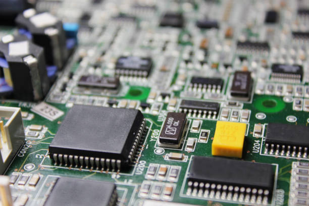
Control the Solder Paste Printing Process
Solder paste printing must be consistent and uniform. Any deformation in the paste application can affect the current distribution of the final assembly or create an open or bridged joint.
The printer should use a clean stencil, the correct squeegee, and a stable board support. Paste volume and position should be checked after setup and monitored during production.
Process control prevents defects such as uneven paste, missing paste, bridges, and shifted prints. It also reduces the number of boards that must be cleaned and reprinted.
Prevent Pad Oxidation
The PCB pad must remain solderable when it reaches the printer. Pad oxidation prevents the solder from wetting the copper and creates poor or intermittent joints.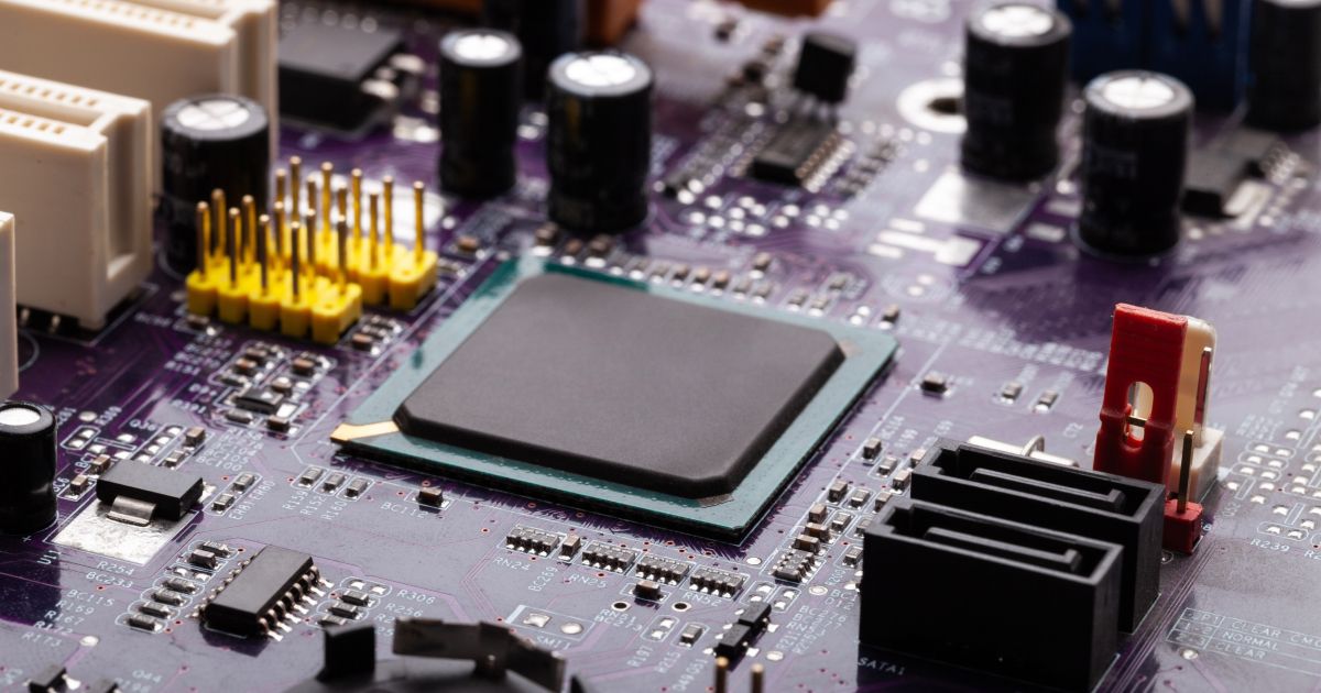
Boards should be stored in their original packaging and used within the recommended shelf life. The surface finish should be compatible with the solder paste and reflow process.
If the pad is exposed to humid air or chemicals, the solderability can be reduced. The incoming board should be inspected for oxidation before it is loaded onto the line.
Check Copper Exposure and Trace Condition
The printed circuit board should not have exposed copper or damaged trace markings in the assembly area. Exposed copper can oxidize or accept solder in the wrong location.
The board layout should be checked for copper trace marks that cross a pad or that can create a false solder connection. A DFM review should find these problems before the board reaches the printer.
Bridging, edge down, deviation, bending, and twisting should all be controlled during PCB fabrication. A warped board cannot be printed or placed with consistent accuracy.
Print From Center to Edge
Solder paste should be printed from the center of the board toward the edges. This direction reduces air entrapment and creates a more even paste deposit.
The printing thickness should be uniform across the whole board. A thin print in one area can create an open joint, while a thick print in another area can create a bridge.
The stencil should be cleaned after the correct number of prints so that paste does not build up in the apertures.
Print speed, pressure, and snap-off distance should be optimized for the board and paste type.
Align Stencil Holes With Board Marks
The mounting holes or fiducial marks on the stencil should match the reference marks on the circuit board. This ensures that the paste is placed only on the pads and does not interrupt later component installation.
The printer vision system should measure the board fiducials before every print. If the board or stencil is not aligned, the print should be stopped and corrected.
A misaligned stencil can put solder paste on the solder mask or leave a pad without paste. Both conditions create defects after reflow.
Control Solder Paste Age and Mixing
When old solder paste is mixed with new solder paste, the recommended ratio should be followed, commonly about three parts old to one part new. The paste should have the same alloy and flux type.
Mixing old and new paste in the wrong ratio changes the flux activity and the paste rheology. The supplier instruction should always be followed.
Paste that is too old or that has absorbed moisture should be discarded. It cannot be repaired by adding flux or solvent.
Control Temperature and Humidity
The application temperature of solder paste should be kept near 25 degrees Celsius. High temperature makes the paste flow too easily, while low temperature makes it difficult to print.
The relative humidity during solder paste printing should normally be between 35 and 75 percent. High humidity can cause moisture pickup, and low humidity can increase static charge.
The printer area should have a thermometer and hygrometer, and the readings should be recorded with the production data.
Inspect Paste After Printing
After solder paste has been applied, the board should be checked with automatic optical inspection or another paste inspection method. The check detects whether an error has occurred before components are placed.
Paste inspection can measure the height, area, volume, and alignment of every deposit. A flying probe test or electrical check may also be used at a later step to verify the circuit.
Early inspection allows the site to correct the printer before a full lot is produced. It also prevents expensive component assembly on a board that has no paste on its pads.
Control Component Placement
Component placement is completed with an automatic surface mounting device. The machine must be calibrated to the required chip installation function before production.
An error in machine calibration can affect the overall quality of the PCB manufacturing process. Calibration should be checked regularly and after any repair or maintenance.
Because the SMD is executed by computer code, the placement program requires careful programming, cross-checking, and editing. The engineer should compare the program with the BOM and the board drawing.
Feeders and the SMD must be installed accurately and interconnected correctly. A wrong feeder position can cause the machine to pick the wrong component for every board.
Perform Error Detection and Commissioning
Error detection, commissioning, troubleshooting, and maintenance should be considered regularly. This prevents device deformation and errors during the first cycle of chip installation.
Before each placement cycle, the settings should be debugged and verified. The machine should run a test board or dry run to confirm that the program, nozzles, and feeders are ready.
The relationship between the device components and the SMD operation path should be analyzed. This helps the engineer identify possible collisions or difficult placement areas before production.
Before commissioning, the operation process should be clear so that system calibration is result-oriented rather than based on trial and error.
Analyze Defect Redundancy
The redundancy of defects should be analyzed to understand when and where errors recur. If the same defect appears in the same board area on many boards, the cause is likely to be a feeder, nozzle, or program issue.
Once the time period and location of the defect are known, the SMD can be calibrated for that specific condition. The correction can be verified with a new test board before full production resumes.
Defect data should be tracked over time so that improvement can be measured. Process control is more effective when it uses data instead of opinions.
Control Reflow Soldering
Reflow soldering melts the solder paste and fixes the installed components in place. The oven temperature and other parameters must be controlled carefully.
The temperature curve and thermal profile must be analyzed so that the solder reaches the required melting temperature. A profile should be developed for the actual board, not copied from a similar product.
The solder joint should form a smooth half-moon fillet shape that indicates a strong connection. A flat, grainy, or incomplete joint should be investigated.
The PCB surface should be checked for false soldering, bridges, solder paste residue, and solder balls after reflow.
Prevent Vibration During Soldering
Vibration and mechanical shock should be prevented during welding. Movement can shift components before the solder solidifies and create distorted or broken joints.
The conveyor and oven should run smoothly without sudden starts or stops. Boards should not be bumped while they pass through the reflow zone.
After the oven, the board should be handled gently until the solder has cooled and gained strength.
The complete process is supported by SMT PCB assembly services that define process control measures for each machine and material.
Solder paste control, placement calibration, and reflow monitoring should be combined with PCBA testing to verify the final assembly.
Process data should be reviewed with quality management procedures so that the next lot starts from a known, controlled condition.
A professional PCB assembly partner can apply these controls across prototypes, low-volume runs, and high-volume production.
Each production lot should be documented with the paste lot, print settings, placement program revision, and thermal profile. If a customer returns a board, the factory can compare the field failure with the production record to find the process condition that may have created the defect.
Conclusion
SMT PCB assembly process control measures prevent errors in solder paste printing, component installation, and reflow soldering. Each step must be defined, measured, and monitored.
Paste inspection, placement calibration, defect analysis, and thermal profiling give the factory the information needed to correct a process before it creates a large quantity of defective boards.
With disciplined process control, SMT assembly provides the efficiency and reliability expected by modern electronic products.


