




SMT Production Line Equipment and AOI Inspection Guide
SMT production line equipment works together to place electronic components on a bare PCB, solder them into place, and verify that the assembly is correct. A complete line may contain loaders, solder paste printers, SPI, placement machines, reflow ovens, wave soldering systems, AOI, X-ray, and unloaders. The exact arrangement depends on the product and required throughput.
Surface mount technology has made it possible to produce the compact circuit boards used in phones, computers, home appliances, automotive electronics, medical devices, and industrial equipment. Components are placed by machines and then soldered in a controlled oven.
This guide describes the main equipment categories on an SMT line and explains how AOI automatic optical inspection is used to find assembly defects.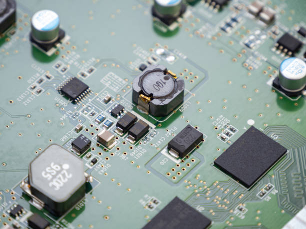
The Core SMT Production Line
A typical SMT line begins with a loader that feeds bare PCBs into the process. The board moves to a solder paste printer, where a stencil deposits paste onto the pads.
After printing, a connection table or conveyor carries the board to the placement machines. Pick-and-place machines take components from feeders and place them on the wet solder paste.
The assembled board then passes through a reflow oven, where heat melts the solder and creates the electrical and mechanical connections. After reflow, the board is unloaded for inspection and testing.
Some lines add a wave soldering machine for through-hole components or for boards that use adhesive and mixed technology. A complete line may also include dispensers for adhesive, underfill, or masking material.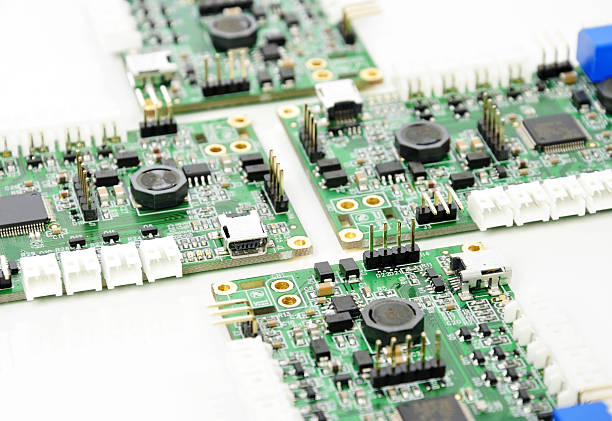
The essential machines for basic SMT production are the solder paste printer, the placement machine, and the reflow oven. Additional equipment is added to improve quality and support special processes.
Production Equipment
SMT production equipment includes solder paste dispensers, stencil printers, placement machines, reflow ovens, and wave soldering systems. Dispensers apply adhesive or paste when printing is not practical.
Solder paste printers control the position and volume of paste deposited on the board. The stencil, squeegee, and printing parameters determine whether the assembly will have consistent joints.
Placement machines may range from a small desktop unit for prototypes to a high-speed modular line for high-volume production. They use vision systems and component libraries to place parts accurately.
Reflow ovens are divided into heating zones with controlled temperature and conveyor speed. The thermal profile must be measured and verified for each product.
Wave soldering equipment is used for through-hole and mixed-technology boards. It creates a molten solder wave that contacts the bottom side of the assembly.
SMT Test and Inspection Equipment
Quality control requires inspection between process steps. Solder paste inspection, or SPI, measures the volume, height, and alignment of paste after printing.
Reflow oven profilers measure the actual temperature of the board as it passes through the oven. The profiler data verifies that each product follows its approved soldering curve.
Automated optical inspection, or AOI, checks components and solder joints after placement or reflow. It can detect missing parts, incorrect orientation, wrong parts, bridges, and poor solder.
In-circuit testing, or ICT, verifies the electrical connections and component values using a bed-of-nails fixture. X-ray inspection finds defects hidden under BGAs and other packages.
Automated test equipment, or ATE, performs functional tests under operating conditions. The right combination of inspection and testing helps find defects at the earliest process step.
Peripheral Equipment
SMT peripheral equipment supports the main line. Solder paste mixers restore the paste to the correct consistency before it is loaded into the printer.
Connection tables and buffer stations control the flow of boards between machines. They allow one machine to pause without stopping the entire line.
Loaders and unloaders store boards in magazines or stacks and move them automatically. Board separators or depaneling equipment divide a production panel into individual circuit boards after soldering.
These peripheral devices improve automation, reduce handling damage, and help the line run continuously.
SMT Parts and Consumables
SMT consumables include solder paste, solder bars, chip adhesive, flux, and cleaning chemicals. The quality and shelf life of these materials affect soldering and reliability.
Machine parts include thermocouples, heating elements, squeegee blades, stencils, nozzles, dispense needles, wave soldering barrels, and feeders. Worn parts should be replaced on a maintenance schedule.
ESD products protect sensitive components. Operators should use anti-static wrist straps, floor mats, work tables, containers, packaging, and detection instruments when handling static-sensitive devices.
Hand tools such as ESD soldering irons, solder pots, chip holders, and cleaning equipment support rework and repair. Each tool should be maintained and calibrated for its process.
Cleaning Equipment
Some assemblies require cleaning after soldering to remove flux residue. Ultrasonic cleaners and PCBA cleaning machines are used when residue can affect performance or reliability.
Cleaning must be matched to the board, components, and flux system. Not every flux is water soluble, and not every component can survive ultrasonic energy.
The cleaning process should be verified so that no cleaning solution remains under components or inside connectors. Drying is an important part of the process.
What Is AOI
AOI stands for automatic optical inspection. It uses cameras and light to inspect the surface of a printed circuit board assembly for visible defects.
AOI can be placed after solder paste printing, after component placement, or after reflow soldering. Each position checks a different stage of the assembly process.
The machine compares the captured image with the expected component position and solder shape. Defects such as missing components, reversed polarity, wrong parts, bridges, and insufficient solder are reported for review.
By finding defects early, AOI reduces the cost of rework and prevents defective boards from moving to later process steps.
AOI Test Method
AOI inspection starts when the detection program is launched. The system scans the PCBA and captures image data from the components and solder joints under inspection.
The image data is compared with preset limits. If the measured value stays within the first threshold, the board is classified as acceptable and its result is saved.
If the measured value exceeds the first threshold, the system performs a second comparison. The second threshold determines whether the deviation is serious enough to reject the board automatically.
When the result is greater than the second threshold, the board is confirmed as defective and the failure is recorded. Boards that fall between the two thresholds are reviewed by an operator before the final decision is made.
This staged method reduces the chance that a clear defect will pass because an operator misread the AOI image.
Operator Review and False Calls
AOI systems are sensitive and can report the same location many times even when the board is acceptable. Operator review is necessary to separate real defects from acceptable process variation.
After a defect is reported, the operator should inspect the location visually. If the component is actually missing, reversed, or misaligned, the board should be marked for repair.
If the board is acceptable, the operator can confirm the result and allow the board to continue. The decision should be recorded so that the process data remains complete.
Misjudgment is a serious risk when the AOI image shows a small or hidden difference. Clear review rules and operator training reduce the number of defective boards that pass into later production.
An improved AOI process should use thresholds that match the actual defect criteria. The system should be programmed to reject definite errors and send borderline results to review.
Inspection Steps in the AOI Program
A robust AOI method begins by starting the inspection program and detecting the components on the PCBA. The system records the inspection data for each location.
The data is then compared with a preset first threshold. If the value is within the normal range, the board is confirmed as good and the result is stored.
If the value exceeds the first threshold, the system checks whether it also exceeds the second threshold. A value above the second threshold is classified as a confirmed defect and the board is rejected.
If the value is only slightly outside the first threshold, the system waits for operator input. The operator may classify the location as good or defective based on visual review.
Every result is stored with the board and process data. This provides a complete trace of what was inspected and how each decision was made.
AOI Limitations
AOI can only inspect what is visible from the camera angle. Solder joints hidden under a BGA body or under a bottom-side component cannot be evaluated by a standard top-side optical system.
AOI does not verify electrical function. A board can pass optical inspection but still contain an open via, a wrong component value, or an internal fault that is not visible on the surface.
For hidden joints and electrical verification, AOI should be combined with X-ray inspection, ICT, or functional test. The combination gives the factory a complete picture of assembly quality.
AOI programs should also be maintained as the product changes. New component finishes, board colors, and solder shapes can change the appearance of an acceptable joint.
Building an Integrated SMT Quality Line
An effective SMT line connects every inspection result with the process that created it. Solder paste printing data, placement data, reflow profiles, AOI images, X-ray images, and test results should be reviewed together.
The first step is to choose a SMT PCB assembly partner that has the necessary equipment for the product. A basic prototype may need only printing, placement, and reflow, while a complex BGA product needs AOI and X-ray capability.
All machines should be included in a preventive maintenance program. Nozzles, cameras, squeegees, stencils, ovens, and fixtures wear with use and affect the inspection result.
The assembly partner should use PCBA testing methods that match the board complexity. Test access, component types, and customer requirements determine whether ICT, functional test, or both are used.
Inspection data should be reported as part of the quality management system. Customers can use AOI yield data, X-ray images, and test records to confirm that their boards were produced under control.
A professional PCB assembly service can also support DIP and mixed technology after the SMT process. The line layout should be planned so that no board is handled more than necessary.
Choosing Equipment for a New Line
New SMT production lines should be sized according to the product mix. High-volume consumer boards need high-speed placement machines, while prototype and low-volume boards may need more flexible equipment.
The factory should plan spare capacity for future products. A line that is optimized for one board may not support components with different sizes, weights, or packaging.
Equipment suppliers should provide training, documentation, and spare parts. Machine uptime depends on operator skill and access to the correct consumables.
Before purchasing, the factory should run sample products on the proposed line and measure cycle time, placement accuracy, and first-pass yield.
Conclusion
SMT production line equipment must be selected as a system rather than as separate machines. Printing, placement, reflow, inspection, and testing all affect final quality.
AOI automatic optical inspection is a valuable quality tool when its thresholds, programs, and operator review procedures are managed correctly. It should be combined with electrical and X-ray inspection for complete assurance.
With the right equipment and process controls, an SMT line can deliver high-quality PCBA products at the speed and volume required by the market.


