Thermal Cycling Testing Of Solder Joints
A solder joint that survives assembly has only proved that it can be made. Whether it will survive the life of the product is a different question, and the standard way to answer it is a thermal cycling test: the assembly is taken repeatedly between two temperatures and the joints are monitored until they fail. The test reproduces, in a few weeks, the damage that a product might accumulate over years of switching on and off.
This article explains what the test measures, how the profile is chosen, how the joints are monitored, and how the result is interpreted.
What The Test Measures
The damage in a thermally cycled joint comes from the difference in expansion between the component and the board. The solder is the most compliant element in the joint, so it absorbs the strain, and the strain accumulates as plastic deformation over each cycle. Eventually a crack starts, usually at the interface with the pad or with the component, and it grows until the joint opens.
The test therefore measures a number of cycles to failure, and the figure is only meaningful with the profile that produced it. A joint that survives 1000 cycles between 0 and 100 degrees may fail after 200 between minus 40 and 125, and quoting a cycle count without the range and the dwell is quoting a number without a meaning.

Range, Ramp And Dwell
The temperature range sets the amount of strain per cycle. A wider range removes more energy per cycle and shortens the life, and the relationship is strong enough that a small change in range changes the result substantially. The range is chosen to bracket the extremes the product will see, including the storage and transport conditions rather than only the operating ones.
The dwell is the time spent at each extreme, and it controls how much of the assembly actually reaches that temperature. A large component with a high thermal mass needs a long dwell to reach the soak temperature, and a test with a short dwell under tests exactly the parts that are most at risk. The ramp rate then controls the rate of strain, and a very fast ramp adds a thermal shock effect that is a separate mechanism from the fatigue that the test is meant to reproduce.
Test Vehicles And Monitoring
The joints are monitored continuously through a daisy chain: the components on the test vehicle are connected in series so that a break in any joint opens the circuit. The resistance of the chain is measured during the test, and a rise above a threshold is recorded as a failure. The threshold matters, since a partially cracked joint may show a resistance change long before it opens and the interpretation depends on which of the two is being counted.
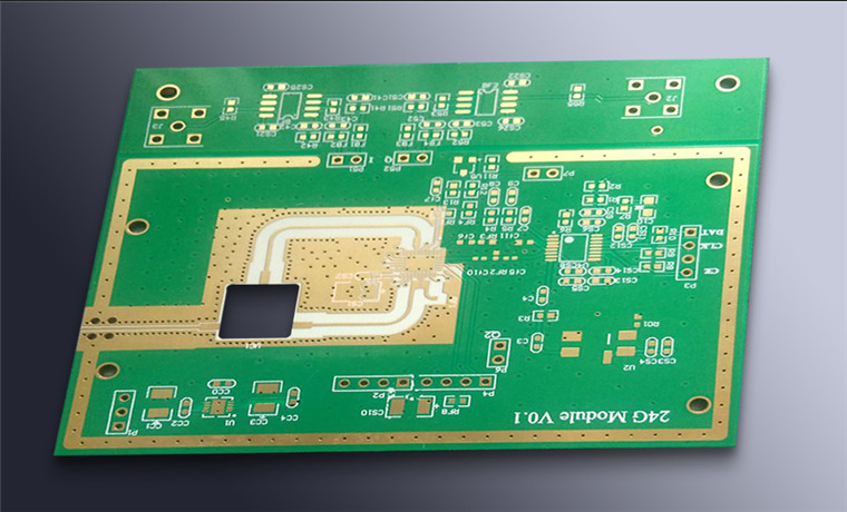
The test vehicle itself has to represent the product. The component size, the pad geometry, the solder volume and the board thickness all affect the life, and a vehicle built with different values tests a different joint. Where a product has several joint types, the vehicle carries one of each and the failures are reported by type rather than as an average.
Failure Analysis And The Distribution
A single test does not give a life, it gives one point. Several samples are tested and the results are plotted as a distribution, and the shape of the distribution describes whether the failures are from one mechanism or from several. A steep distribution indicates a consistent process and a single dominant mechanism, while a wide one indicates that the samples differ in a way that matters.
The failed joints are sectioned and examined. The position of the crack, the presence of intermetallic growth and the grain structure of the solder all identify the mechanism, and a joint that failed with a thick intermetallic layer has a different remedy from one that failed in the solder. The mechanisms that the sample reveals are described under intermetallic growth and solder joint reliability.
Choosing The Conditions
The conditions come from the product and from the standards that apply to its industry. A consumer product may be tested between 0 and 100 degrees, an automotive product between minus 40 and 125, and a product that will be stored in an unheated warehouse needs a lower extreme than one that is not. The number of cycles is chosen so that the test is long enough to produce failures in the weakest joints, which usually means testing until a defined proportion of the samples has failed.
The test also has to account for the assembly process, since the joint carries the thermal history of the reflow as well as the cycling. A vehicle that was reflowed twice has a different starting point from one that was reflowed once, and the difference is large enough to appear in the result. The alloy contributes in the same way, and the differences are described under lead free versus leaded solder and the process that produces the joint under PCBA development process.
What The Test Does Not Cover
A thermal cycling test does not reproduce vibration, mechanical shock, humidity or corrosion, and a joint that passes it can still fail in service from another mechanism. A complete qualification covers each of those separately, and the combination of them is covered by the environmental tests rather than by the cycling test alone.
It also does not reproduce the effect of a single large overload, such as the bending of a board during depanelisation or a drop. Those produce a crack immediately, and the crack then grows under the cycling. Where a product has both, the cycling test on a board that has been through the assembly process is more representative than one on a specially prepared vehicle. The protection that a coating gives against the humidity part of the environment is described under conformal coating and board protection.
Process Control and Verification
On a design of this kind, strain is the item that decides how the rest of the board is arranged. Running a first article through the same checks as the production panel confirms that the two agree, and that comparison is the cheapest form of process control available at prototype stage. Keeping a sample from the panel turns a dispute into a measurement, because the same coupon can be re-examined by both parties without rebuilding the batch.
FAQ
How many cycles should a joint survive? The figure comes from the product requirement and from the industry standard, and it cannot be chosen in isolation. What matters is the number at the specified range and dwell, together with the failure criterion.
Is a resistance rise a failure? It is if the criterion says so, and it is usually the criterion of choice because it detects a partial crack before it opens. The threshold should be stated, since a joint that rises by 20 percent has not failed in the same sense as one that has opened.
Does the test destroy the boards? The test vehicle is destroyed, and the product boards are not tested in this way. The vehicle is built with the same materials and processes so that the joints behave in the same way.