Spring Probe Contact Resistance in ICT: Wear and Limits
A spring probe is a small compliant contact that presses onto a test point and carries the measurement current. Its contact resistance adds to the resistance being measured, so a probe that has worn or become contaminated changes the result of the test rather than failing outright. That is what makes probe wear a quality issue: the fixture keeps producing results and the results slowly stop meaning what they did.
The resistance of a healthy probe is a few tens of milliohms, and the limit for a test fixture is a total budget that includes the probe, the wiring and the connector. When a single probe reaches a fraction of that budget, the measurements it takes become unreliable even though the probe still shows continuity on a simple check.
Why Contact Resistance Matters
In circuit test measures resistance and impedance between nodes and compares the result with a stored value. If the probe adds 200 milliohms, every measurement that probe makes is biased by that amount. A low value resistor then reads out of tolerance, and a marginal joint reads as a failure or as a pass depending on the direction of the error.
The effect grows with the resolution of the test. A measurement of a 10 ohm resistor tolerates a large probe resistance, while a measurement of a 50 milliohm path or a continuity check on a power plane does not. Fixtures that test low impedance nets need their probe resistance controlled much more tightly than fixtures that test only presence and value.
What Sets the Resistance
The contact resistance is the sum of the constriction resistance at the points where the metals touch and the film resistance of whatever covers those points. A sharp tip pressed hard into a soft pad creates more contact points and a lower resistance, while a blunt tip on an oxidised pad creates few and a higher one.
Spring force and travel set how hard the tip presses, and therefore how much of the film it breaks through. Both fall as the spring ages, and both are measured at the fixture rather than assumed from the drawing. The metallurgy of the tip also matters, since a hard tip resists wear and a soft one deforms.
Probe Wear and Its Progress
Probe wear is a gradual process. The tip flattens, the geometry that concentrates the pressure is lost, and the contact area grows while the force per unit area falls. The resistance rises slowly at first and then more quickly, and the change is usually visible only in the trend rather than in a single measurement.

Wear is accelerated by contamination on the test point, by abrasive finishes and by a fixture that is set with too little travel. A probe that bottoms out, or one that barely touches, wears faster than one working in the middle of its travel range. The service life quoted by the supplier assumes correct travel, and the notes on probe selection describe how that range is chosen.
Tip Styles and Contact Area
Tip styles trade contact quality against damage. A crown tip cuts through oxide and contamination and gives a stable resistance, at the cost of a small mark on the pad. A conical or a flat tip is gentler and depends more on a clean surface. The choice follows the finish and the rework policy of the product.
A crowned tip on a soft finish removes a little material at every cycle, so the resistances of individual probes diverge as the fixture runs. Where the fixture tests the same board many times, tip marks accumulate and the pad becomes an unreliable contact. The test point design side of this is described in the notes on test point design.
Spring Force and Travel
The spring supplies the force, and the travel is set by how far the fixture closes beyond first contact. A fixture closed to 60 percent of the available travel gives the spring room to work and keeps the force inside its design range, while one closed to the limit compresses the spring solid and damages it.
Force falls as the spring ages, and a fixture in daily use can lose a measurable share of its force over a year. The check is a measurement of the force at the working travel on a sample of probes, repeated on a schedule, rather than a judgement based on how the fixture feels when it closes.
Cleaning and Contamination
Flux residue, solder paste and conformal coating on a test point raise the contact resistance and accelerate tip wear. Cleaning the probes on a schedule is therefore part of test floor maintenance and not a cosmetic task, and the method has to remove the contamination without deforming the tip or spreading it into the barrel.
Cleaning also has a cost. A solvent that attacks the barrel lubricant shortens the life of the probe, and mechanical cleaning with an abrasive wears the tip. The practical method and its effect on the measurement are described in the notes on probe cleaning.
Measurement and Verification
Probe resistance is verified by measuring a known low resistance through the probe, either with a dedicated fixture check or with a test program that runs a shorting block. The result should be recorded per probe position rather than as a fixture average, because the failing probe is the one that matters.
A four wire measurement removes the lead and connector resistance from the reading, which is the only way to see the probe on its own. Where the fixture is not wired for four wire measurement, the check compares probes against each other, and a probe that is much higher than its neighbours is a candidate for replacement. The comparison method is the same discipline used in bare board test.
Replacement Criteria
The replacement decision should be based on a resistance limit and a visual condition rather than on a cycle count alone. A probe that reaches the limit is replaced even if it looks clean, and one that is damaged or that has lost its plating is replaced even if its resistance is acceptable, because the next stage of wear will be faster.
Replacing probes in sets, or at least in the rows that share a common wear pattern, keeps the fixture consistent. Replacing one probe at a time is cheaper per event and leaves the fixture with a mixture of ages, which makes the trend harder to read and the next failure harder to predict.
Records and Trending
The records are the probe type, the position, the measured resistance, the cleaning events and the replacement date. With those fields, the fixture history shows which positions wear fastest, and the pattern usually points to a product feature: a sharp corner, a heavy copper area or a test point that receives less solder.
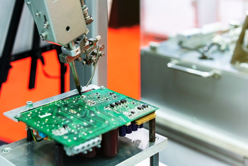
Trending the resistance of the worst positions over time converts a maintenance task into a prediction. A fixture that reaches its limit after a known number of cycles can be serviced between production runs rather than during one, and the escapes that come from a marginal probe are removed. The alternative test methods that avoid probes entirely are compared in the notes on flying probe and ICT.
FAQ
What contact resistance is acceptable? It depends on the lowest resistance the fixture measures. A common budget is well under 100 milliohms per probe, and low impedance tests need less.
Do probes fail suddenly? Rarely. The resistance rises gradually, so the failure appears as a drift in measurements rather than as a loss of contact.
How often should probes be cleaned? At an interval set by the contamination the product leaves, and after any run that produces visible residue on the fixture.