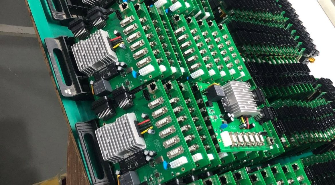
Junction Temperature: Thermal Design Practice for Electronic Assemblies
An active electronic device is a source of heat that has to be removed, and the practice of thermal design is mostly about identifying which of the series resistances dominates and addressing that one rather than the others. The exercise is short and the alternative is a product that fails in the field.
Starting With the Dissipation
The first quantity to establish is the power dissipated in each device, which is rarely the same as the rated maximum. A regulator dissipating a fraction of its rating may still be the hottest component on the board if its package has a high thermal resistance.
The dissipation comes from the datasheet, from a measurement or from a calculation, and all three are acceptable provided the condition is stated. A figure quoted at full load in still air is not the same as one at half load in an enclosure. Our thermal management notes describe how the figure is used.
Junction Temperature and Its Limit
The junction temperature is what has to be kept below the limit, not the case temperature. The two are related by the thermal resistance from junction to case, which is a datasheet parameter, and by the power dissipated.
The margin between the calculated junction temperature and the limit is the design margin. A design that reaches ninety per cent of the limit in the laboratory will exceed it in a warmer enclosure, which is where most thermal failures originate.

The Series of Resistances
Heat flows from the junction to the case, from the case to the board through the solder joint, from the board to the ambient through convection and radiation, and from the board to any attached heatsink. Each of those is a resistance, and they add.
Identifying the largest one tells you where to work. If the junction-to-case resistance dominates, no amount of board copper will help; if the board-to-ambient resistance dominates, then the copper area and the airflow are the levers.
Copper Area and Spreading
Copper spreads heat laterally, and the spreading resistance falls as the area grows until the board itself becomes the limit. Beyond that point, adding copper only lowers the temperature slightly.
The spreading can be improved by using a heavier copper layer, by adding a plane beneath the device, or by connecting the device to a larger area through thermal vias. Each of those changes a different part of the path.

Airflow and Orientation
Forced airflow reduces the convection resistance dramatically, and the improvement is worth more than any change to the board. Where a fan is present, the thermal design should be verified with the fan running and with it stopped, because a fan failure should not create a hazard.
Natural convection depends on orientation, with a vertical board shedding heat more effectively than a horizontal one. Where the product can be installed in more than one orientation, the worst case governs.
Heatsinks and Interface Materials
A heatsink adds a path from the component to a larger surface, and the interface between them is filled with a material that displaces the air. The air gap is the dominant resistance in a poorly assembled joint, which is why the mounting force and the flatness both matter.
The heatsink is only useful when the component-to-heatsink path is not itself the bottleneck. Where the package has a high thermal resistance to its own case, a heatsink cannot compensate.
Thermal Cycling and Material Stress
Repeated heating and cooling fatigue the joints, and the fatigue is driven by the temperature excursion rather than by the absolute temperature. A design that runs warm but stable may outlive one that runs cool but cycles continuously.
The design response is to reduce the amplitude where possible and to make the joints more compliant where it is not. Component placement relative to the neutral point of the board is one of the few levers available at the layout stage.
Verification
Thermal verification is done by measurement on a representative assembly in a representative enclosure, with the loads applied. A board measured on the bench in still air will be cooler than the same board inside a sealed housing.
The measurements should be taken at the points identified in the calculation, so that the model can be corrected. A measurement that confirms the calculation is as useful as one that contradicts it. Our test coupon notes describe the related verification structures.
Process Control and Verification
On a design of this kind, thermal cycling is the item that decides how the rest of the board is arranged. Running a first article through the same checks as the production panel confirms that the two agree, and that comparison is the cheapest form of process control available at prototype stage. Keeping a sample from the panel turns a dispute into a measurement, because the same coupon can be re-examined by both parties without rebuilding the batch.
Reviewing the design before the data is released is cheaper than correcting it after the panel is in the tank, because every step downstream inherits the decision made at the front end. Documenting the assumption is part of the design work, and a short note on the drawing prevents a question that would otherwise arrive a day later and cost a day of schedule.
The process window is set by the narrowest step in the flow, so an improvement anywhere else shows up as margin rather than as yield until that step is addressed.
Related reading: our fabrication notes, board quality and design release notes cover the same ground.
Process Control and Verification
On a design of this kind, thermal cycling is the item that decides how the rest of the board is arranged. Running a first article through the same checks as the production panel confirms that the two agree, and that comparison is the cheapest form of process control available at prototype stage. Keeping a sample from the panel turns a dispute into a measurement, because the same coupon can be re-examined by both parties without rebuilding the batch.
Reviewing the design before the data is released is cheaper than correcting it after the panel is in the tank, because every step downstream inherits the decision made at the front end.
Process Control and Verification
On a design of this kind, thermal cycling is the item that decides how the rest of the board is arranged. Running a first article through the same checks as the production panel confirms that the two agree, and that comparison is the cheapest form of process control available at prototype stage. Keeping a sample from the panel turns a dispute into a measurement, because the same coupon can be re-examined by both parties without rebuilding the batch.
FAQ
How much copper area is enough? Enough that the spreading resistance is no longer the dominant term in the path. The way to find that point is to estimate each resistance, and the answer is usually that the convection resistance dominates once the copper area reaches a few square centimetres.
Are thermal vias always necessary? They are necessary where the heat must pass from a surface pad into an internal or opposite-side plane. Where the device sits directly on a large area of copper on the same layer, the vias add little.
What does gopcb check on a thermally critical design? We check the copper area beneath the device, the thermal via array and its connection to the plane, the thermal relief on the joints, the copper balance of the stack and the flatness of the finished board, because a warped board will not sit against a heatsink.