Through Hole Opening Window: Solder Mask Design and Cost
Why the Through Hole Opening Window Matters
In printed circuit board design, small details often decide the performance, reliability and final cost of a product. One of the most important yet easily overlooked details is the through hole opening window. This is the area on the solder mask layer that is deliberately left open around a plated through hole pad so the bare copper is exposed for soldering or inspection. In PCB manufacturing, getting this window right is the difference between a clean solder joint and a board that fails in the field.
Whether you design consumer electronics, industrial controls or automotive electronics, understanding the through hole opening window helps you improve soldering quality, make boards easier to inspect and keep long term reliability high. This guide explains what the window is, how it is made, the different types, the design rules that control quality and what it costs in 2026.
What Is a Through Hole Opening Window?
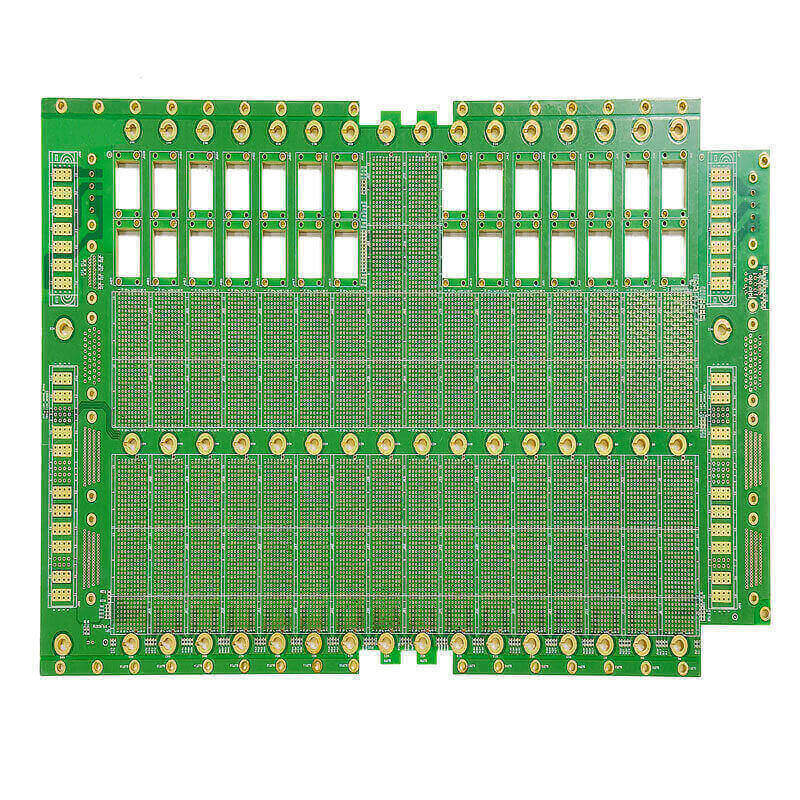
A through hole opening window is the opening in the solder mask layer that exposes the copper pad around a through hole, either a plated through hole or a non plated hole. Three elements define it: the through hole itself, the copper pad that surrounds the hole and the opening where the solder mask is removed.
In simple terms, the window keeps the green solder mask away from the pad so solder can wet the copper and form a strong connection. Without the window, the solder mask would cover the pad and block solder from reaching it, which would produce poor joints and unreliable connections.
How the Through Hole Opening Window Is Made
The solder mask is applied over the copper layer to protect the circuit and prevent solder bridges. At every place where a solder joint is needed, the mask must be removed. The typical sequence begins with covering the board in liquid or dry film solder mask, then exposing it through a photographic film using ultraviolet light, developing the board to wash away the mask over the pad areas and finally curing the remaining mask at high temperature to form a tough protective layer.
Several factors decide whether the window is complete and accurate. Solder mask registration is typically held to a tolerance of plus or minus 50 to 75 micrometers, and the spacing between the pad and the opening must be set carefully. Drill to pattern alignment also matters, because a drill that wanders relative to the artwork can leave an opening that is too small, too large or shifted off the pad. Together these factors determine whether the window is centered and whether the joint will solder reliably.
Types of Through Hole Opening
Full opening. The pad is fully exposed with no solder mask covering it. This is best for wave soldering and manual soldering, where the solder needs to wet the entire pad. It also makes visual and automated inspection easier because the whole joint is visible.
Partial opening. Only part of the pad is exposed. This is common in high density PCB designs where the board is crowded and the designer wants to limit the opening area. It is more sensitive to alignment, since a small shift can leave too little exposed copper for a sound solder joint.
Tented via. The via is completely covered by solder mask. Tenting keeps solder out of the hole and is used for signal vias that do not need to be soldered. The tradeoff is lower protection against contamination compared with a filled via.
Plugged via. The through hole is filled with resin or conductive material. This approach is common on HDI and multilayer boards and gives the most robust protection, while still allowing a pad to be placed over the via when needed.

Core Benefits of the Through Hole Opening Window
Better soldering. An accurate opening lets solder fully wet the pad and form a strong, void free joint in wave soldering and manual soldering. This reduces cold joints, incomplete wetting and expensive rework.
Easier inspection. When the pad and hole are clearly exposed, visual inspection and automated optical inspection can check the joint reliably. A clean opening reduces false rejects and speeds up quality control.
Consistent reliability. Properly controlled openings prevent accidental solder mask over the pad and stop solder from wicking into unwanted areas, which protects the board over its service life in vibration and thermal cycling.
Better manufacturability. A window designed with the fabricator in mind makes the board easier to build at high yield, lowering the cost per board and reducing the number of engineering change requests.
Design Rules for a Reliable Opening
Start with adequate solder mask registration. If the supplier holds a registration tolerance of plus or minus 50 to 75 micrometers, design the opening so that even at the worst case offset the pad remains fully exposed. Keep the annular ring large enough so the window never cuts into the hole, and leave the correct clearance between the pad and the surrounding copper so solder does not bridge between adjacent features.
For high density layouts, communicate the alignment budget early. Share the drill table, the copper layer data and the solder mask layer with the fabricator and review the stack up with a PCB design and layout check. Confirm that drilled holes match the artwork so the pad and opening stay concentric, and specify the window class for every via and through hole so the shop knows whether to leave it open, tent it or plug it.
Through Hole Opening Cost in 2026
Cost is driven mainly by layer count, hole size, hole count and board surface finish. A simple two layer board with standard through holes costs far less than a dense multilayer board with many small holes and tight registration requirements. Using expensive surface finishes such as ENIG on a board where the finish does not add value raises cost without improving the window quality.
In 2026 a typical two layer board with through hole windows adds only a small premium, while a high density board with fine pitch openings and a strict registration budget can add meaningfully. Solder mask savings rarely justify a poor opening, so it is usually better to spend on registration and surface finish than to cut corners on the mask itself.
Because price depends on volume and the specific design, asking for a quote that includes layer count, hole count and surface finish gives a more accurate picture than a flat per board estimate.
Common Through Hole Opening Problems
Opening too small or shifted. Caused by poor solder mask registration or misaligned drill data. Tighten the registration budget and ensure the drill and artwork share the same origin and layer alignment.
Solder mask over the pad. Caused by an undersized window. Increase the opening or enlarge the pad so the mask never covers the joint area.
Solder wicking into the hole. Caused by an oversized opening or a via that should have been tented or plugged. Classify each hole correctly and choose tenting or plugging for vias that must stay sealed.
Bridging between pads. Caused by insufficient clearance between pads. Add spacing and keep the opening confined to the pad instead of bleeding into the surrounding copper.
FAQ
What is a through hole opening window? It is the open area on the solder mask that exposes the copper pad around a through hole so solder can wet the pad.
What is the difference between a tented via and a through hole opening? A tented via is fully covered by solder mask to keep solder out, while a through hole opening exposes the pad for soldering.
How much registration accuracy is needed? Solder mask registration is typically plus or minus 50 to 75 micrometers, so the opening must allow for that offset.
Do HDI boards need through hole openings? High density boards often prefer plugged vias with a controlled opening for the best protection and reliability.
Get a Reliable Through Hole Opening Design
The through hole opening window is a small feature with a big impact on soldering quality and reliability. Design it with the fabricator, control your registration and alignment, and classify every hole correctly so the right opening, tenting or plugging is applied. Combine that with through-hole PCB assembly and PCBA testing to verify every joint before it ships. Contact gopcb for stack up review, design support and a through hole opening quotation for your next project.