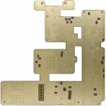
Ultra-Thin PCB Design: Optimizing a 0.15 mm Board
A 0.15 mm board is thinner than a sheet of card stock and roughly one third the thickness of a conventional four-layer stackup. That single change ripples through every decision that follows, from which base material can survive the process to how the panel is handled between operations. An ultra-thin PCB is not simply a thinner version of a normal board.
What 0.15 mm Changes
Thickness affects three things at once: mechanical stiffness, the geometry available for controlled impedance, and thermal spreading capacity. A thin board bends easily, provides very little copper cross-section for heat, and places the reference plane so close to the trace that impedance is dominated by the dielectric thickness.
The benefits are real, which is why the construction exists. Weight and volume fall, the short vertical distance between layers improves via inductance and signal integrity at high frequency, and a flexible base can fold into enclosures that a rigid board cannot enter.
Material Selection
Standard FR-4 becomes marginal at this thickness because its mechanical strength and dimensional stability both suffer. Polyimide is the usual answer for flexible and rigid-flex designs, offering high temperature resistance, good mechanical toughness and a well characterised coefficient of expansion.
Where the board stays rigid, a thin high-frequency laminate or a reinforced polyimide with a low coefficient of thermal expansion is a better match. The key property is dimensional stability during lamination, because a base that moves while the layers are bonded will not register with the inner layers it must connect.
Trace Width, Spacing and Current
Thin boards usually carry thin copper. Reduced copper weight raises resistance for a given width, so a current-carrying trace that was comfortable on a 1.6 mm board may be marginal on a 0.15 mm equivalent. The trace width to current calculation should be repeated rather than assumed from the earlier design.
Spacing matters as much as width, because at fine geometry the risk of an etch-related defect rises. Keeping conductors at the widest spacing the routing will allow, and avoiding long parallel runs, improves both yield and crosstalk performance at the same time.
Stackup and Layer Planning
Impedance targets have to be resolved against the available dielectric thickness. When the dielectric is very thin, a 50 ohm trace becomes narrow, which increases conductor loss and makes the etch tolerance more significant as a proportion of the width. Working the geometry before the stackup is fixed avoids a redesign later.
Layer transitions are the other constraint. Blind and buried vias save space but cost process steps, and microvias are normally required for the highest density. The rules for blind and buried via stack selection matter more here than on a thick board, because there is no spare depth to absorb a badly chosen via structure.

Thermal Management
With little copper volume and no thick core to spread heat, thermal design becomes local. A thermal via array under a power device is usually the only path with acceptable resistance, and its effectiveness depends on the pad area it connects to and on the copper on the far side of the board.
Where the board cannot spread heat itself, the enclosure must. Thermal interface material, a metal stiffener or a direct bond to a chassis all move heat out of the board, and planning that interface early is easier than adding it after the mechanical design is frozen.
Imaging and Fine-Line Definition
Fine features on a thin substrate demand better imaging than a conventional process. Direct imaging removes the film-to-panel contact that can distort a pattern, and it holds registration more accurately across a panel that is likely to move slightly during handling.
Photoresist choice matters for the same reason. A thinner, more uniform resist gives better resolution and cleaner sidewalls, and on a thin board those gains translate directly into a usable process window rather than a marginal one.
Drilling and Microvia Formation
Mechanical drilling struggles at the small diameters this construction requires, so laser drilling is the standard method for microvias. It produces clean, small holes with minimal mechanical stress, which matters when the surrounding material is thin enough to deform.
The trade is process complexity. Laser-drilled holes need suitable surface preparation and a plating process that fills or covers them reliably, and the resulting stackup usually requires sequential lamination. Those steps define the practical limit on how many microvia layers a design can justify.
Lamination, Warpage and Handling
Warpage is the dominant yield risk. Thin panels distort under their own lamination pressure, and any imbalance in copper distribution or in the arrangement of the layers is amplified. Balanced copper, symmetric stackups and a controlled press cycle are the standard countermeasures.
Handling is the second risk. Thin panels need carriers and rigid frames to travel through plating, etching and inspection lines, and every transfer is an opportunity for a crease or a tear. The design constraint that follows is simple: keep features away from areas that handling equipment must grip. The underlying behaviour of these materials is covered in the notes on dimensional stability and expansion.
Surface Finish and Verification
Surface finish has to protect fine features without adding thickness. Electroless nickel immersion gold and immersion silver are the usual choices, offering flat surfaces that suit fine-pitch assembly and good shelf life without the thickness variation of a thicker metallic coating.
Verification follows the same logic as the design. Automated optical inspection handles visible defects, X-ray inspection finds problems in hidden vias and joints, and electrical test confirms connectivity. On a thin board, inspection is not optional, because a defect that would be cosmetic on a thick panel can be structural here.
Design Review Before Release
An ultra-thin design rewards a structured review more than a conventional board does, because the failure modes are less forgiving. The checklist should cover the base material and its coefficient of expansion, stackup balance, copper distribution across the panel, minimum feature size against the fabricator capability, and the drilling strategy for every layer transition.
It should also cover handling. Deciding where the panel may be gripped, which areas can carry a stiffener and whether the assembly process needs a carrier is a design decision that is cheap to make at the drawing stage and expensive to discover on the line.
Finally, the review should confirm the thermal path. A thin board spreads very little heat, so every power device needs a deliberate route from its pad to a larger copper area, a thermal via array or a mechanical interface. Leaving that to the assembly stage usually means the enclosure has to absorb a problem the board could have solved by itself.
Working With the Fabricator Early
Thin constructions sit at the edge of many process windows, so the fabricator capability table is a constraint worth consulting before layout rather than after. Asking which minimum dielectric thickness, which copper weight and which microvia diameter are routinely produced turns a difficult design into a routine one and removes most of the schedule risk.
It is also worth agreeing the panel format in advance. Panel size, rail width and tooling hole arrangement determine how the board travels through every operation, and a design that respects those conventions gets better yield than one that treats them as an afterthought.
FAQ
Can a 0.15 mm board be assembled in a standard line? Usually yes, with a carrier or stiffener that gives the panel rigidity during printing and placement. Without one, the board can flex enough to disturb paste deposition.
Is FR-4 ever acceptable at this thickness? For short-life products in benign environments, sometimes. For anything requiring thermal cycling, repeated flexing or long-term reliability, polyimide or a low-expansion laminate is the safer choice.
Do microvias require sequential lamination? Microvias between the outer layer and the first inner layer do not. Anything deeper normally does, which is why most designs keep microvias in the outer layers and use plated through-holes for deeper connections.