Ultrasonic Transducer: Design Rules and Process Limits
An ultrasonic transducer converts an electrical burst into pressure waves and converts the returning echo back into a voltage. The same ceramic element does both jobs on a simple ranging sensor, and the circuit has to drive it hard for a few cycles and then listen for a signal thousands of times smaller without being deafened by its own transmission.
The Element and Its Equivalent Circuit
A piezoelectric transducer behaves electrically as a capacitor in parallel with a resonant mechanical branch. The capacitor is the plate capacitance, usually a few nanofarads, and the mechanical branch has a series inductance, capacitance and resistance that together set the resonant frequency.
At the resonant frequency the mechanical branch presents a low resistance and the element draws its greatest current. At other frequencies the plate capacitance dominates and the element looks almost purely capacitive, which is why a driver designed for one frequency behaves badly at another.
The quality factor of the resonance is high, typically tens. That gives a narrow bandwidth and a slow decay after the drive stops, which limits how soon the receiver can listen and therefore how close the sensor can measure.
Driving the Element
A simple drive is a square wave applied through a series resistor or a transformer. The square wave contains energy at the resonant frequency, and the element’s own selectivity rejects the rest. It is cheap and it works, at the cost of drive current that produces heat rather than sound.
A half bridge or a full bridge of field effect transistors drives the element with a defined voltage and recovers the energy that the element returns between cycles. The full bridge doubles the applied voltage and suits a low supply, while the half bridge needs fewer parts.
The drive waveform should be shaped rather than switched abruptly. A series inductor slows the edges and stores the energy that is returned, and the result is more acoustic output for the same supply current. The transformer used in many designs does the same job and steps the voltage up at the same time.

impedance matching
The transducer is not a fifty ohm load, and the cable between the driver and the element is often a twisted pair of unknown impedance. impedance matching in this context means making the driver see a load it can drive efficiently, not matching to a standard transmission line.
A series inductor tunes out the plate capacitance at the operating frequency. The value is chosen so that the inductor resonates with the capacitance at the drive frequency, which brings the load impedance close to resistive and reduces the current the driver has to supply.
A transformer with a turns ratio of ten or more is the classic solution for a high voltage drive. It matches the low impedance driver to the high impedance element, and it allows a five volt supply to produce a hundred volts or more across the ceramic, which is what a long range sensor needs.
burst excitation and Ringing
Burst excitation means applying a fixed number of cycles and then stopping. The number of cycles sets the energy in the pulse and the width of the echo envelope: a short burst gives better range resolution, a long one gives more energy and a stronger echo.
After the burst the element continues to ring at its resonant frequency, and the amplitude decays with the quality factor. The receiver must not be listening while the residual signal is larger than the echo, so the drive and the receive path are switched, or the receiver is muted for a fixed time.
Shortening the ring is the main design trade in a close range sensor. A damping resistor across the element reduces the quality factor and shortens the ring, at the cost of acoustic output. Some designs use a switchable damping resistor that is only connected during the receive window.
receiver protection
The receiver input sees the full drive voltage during transmission unless it is protected. A pair of clamp diodes to the supply rails, a series resistor and a capacitor form the usual network, and the resistor also limits the current into the amplifier when the clamp conducts.
The clamp must be fast enough to act at the drive frequency rather than only at direct current. An ordinary silicon diode with a slow recovery conducts late and lets a spike through, while a small signal Schottky diode responds quickly and clamps at a lower voltage.
A better approach is to disconnect the receiver during transmission. A switch or a transistor in series with the input, or the drive circuit itself arranged to short the receiver input, keeps the amplifier out of the high voltage path entirely.
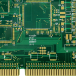
<img src="https://www.gopcba.com/wp-content/uploads/2026/08/hdi-pcb-design-guidelines-11-b6900f71.webp" alt="Burst driver stage and matching network layout for an ultrasonic sensor” />
The Receive Amplifier
The echo signal at the receiver is a few millivolts immediately after the burst and falls to tens of microvolts at the far end of the range. The amplifier therefore needs a high gain and a low noise figure, and often a time varying gain that increases as the echo window progresses.
A time varying gain compensates for the spreading and absorption of the wave in air, which reduce the echo amplitude with distance. Without it, a fixed threshold detects far objects and misses near ones, or the opposite, depending on where the threshold is set.
Band pass filtering around the resonant frequency rejects the broadband noise of the environment. The filter has a narrow band, so its group delay is long, and the delay has to be stable with temperature or the distance reading drifts with the weather.
Frequency, Range and Environment
The operating frequency trades range against resolution. Forty kilohertz gives a long range and a wide beam, while two hundred kilohertz gives a narrow beam and fine resolution over a short distance. The absorption of sound in air rises sharply with frequency.
Temperature changes the speed of sound by about six tenths of a percent per degree, which is a distance error of the same order unless it is compensated. A temperature sensor next to the transducer is cheaper than the error it removes.
Wind and humidity affect the measurement as well. A cross wind deflects the beam and reduces the echo, and a very dry atmosphere absorbs more energy. A sensor specified in a laboratory does not always perform the same way in an outdoor installation.
Layout, Grounding and Verification
Keep the high voltage drive loop physically small and away from the receiver input. The two circuits share the same transducer on a single element sensor, so the drive current is milliamps while the echo is microvolts, and a shared ground impedance is enough to couple one into the other.
Use a separate return for the drive stage and join it to the analogue ground at one point. The general approach to keeping a large signal out of a small signal path is the same as in any mixed signal design and is set out in our guide to mixed signal board design.
Verify the sensor with a target at a known distance and an oscilloscope on the amplified echo. Record the amplitude at several distances, because the shape of that curve shows whether the time varying gain is right, and the release checks that keep the assembly consistent are collected in our PCB design release checklist.
Common Faults and Their Causes
No echo at any distance but a clean burst points to the receiver path: check the protection network, the amplifier gain and the mute timing. A shorted clamp diode, or one that never turns off, kills the signal silently.
An echo that appears at a fixed short distance regardless of the target is usually the ring of the transducer being detected. Increase the damping, lengthen the mute window, or reduce the burst length until the residual decay is below the threshold.
A reading that drifts with temperature, or that changes when the transducer is touched, points to a mechanical or matching problem rather than to the electronics. Confirm the resonant frequency of the assembled unit with an impedance measurement, and compare it with the drive frequency.
Related reading: our fabrication notes, board quality and design release notes cover the same ground.
FAQ
Why do I get no echo at all? Check the receive path protection network first. A clamp diode that is conducting, or an amplifier that is still muted, gives exactly this symptom.
How many cycles should the burst contain? Enough to build up the resonance, typically five to fifteen. More cycles give a stronger echo and a wider envelope, which reduces the range resolution.
Do I need a transformer to drive a transducer? Only for long range. A direct drive from a bridge works over short distances, while a transformer gives the higher voltage that a long range sensor needs.