
Water Heater PCB: Design for Mains Powered Appliances
A water heater control board lives in an environment that most electronics never see: mains voltage on the same substrate as a microcontroller, condensation on the surface for part of every day, and an ambient that rises every time the element energises. Designing a water heater PCB is mostly about keeping the mains domain and the low voltage domain genuinely separate.
What the Board Controls
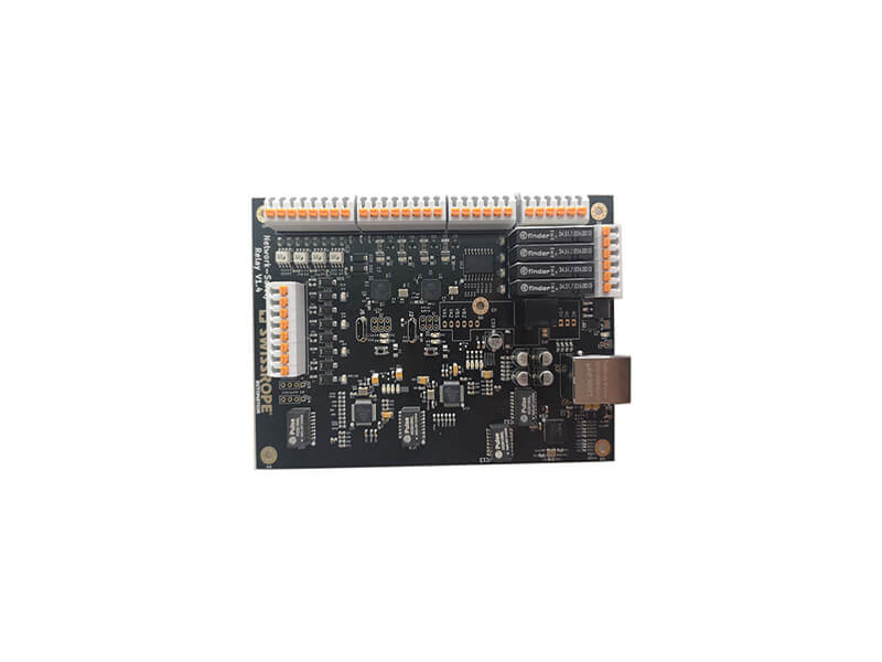
The low voltage side carries the microcontroller, the temperature sensing, the user interface and the communications interface if the appliance is connected. The mains side carries the supply, the relay or triac that switches the element, the safety cut-out and the connections to the heating element, the thermostat and the flow sensor.
The two domains meet only at the isolation barrier and at the switching device. Everything about the layout follows from keeping that boundary unambiguous, because a board that works on the bench and leaks across the barrier will fail a safety test or, worse, pass it and degrade later.
Creepage and Clearance
Mains voltage requires a defined creepage distance along the surface and a defined clearance through air between the two domains, and the required values depend on the working voltage, the pollution degree and the material group of the laminate. In a wet appliance the pollution degree is usually the harshest category, which pushes the required distances up.
Practical measures include a routed slot that interrupts the surface path between the domains, a physical barrier of solder mask free laminate, and keeping the mains copper away from the board edge. Coating the assembly reduces the surface requirement under some standards, but only when the coating is applied and cured to specification. The general principles are covered in conformal coating and board protection.

Switching the Load
A relay is the traditional choice because it provides isolation when open and its failure modes are well understood. The coil requires a relay driver transistor and a freewheeling diode, and the drive current has to be available at the moment of switching, which for a latching relay may be a short pulse rather than a continuous current.
A triac or solid state relay switches faster and does not wear out, but it introduces a leakage path when off and needs a snubber network or a zero crossing drive to control conducted emissions. Its heat has to be managed as well, since the dissipation is continuous rather than transient. The current carrying traces on either device are sized from the load current and the allowable rise, following the calculation in trace width and current calculation.
Component Selection for a Wet Environment
Every component on the mains side has to be rated for continuous mains operation and for the transient the installation can produce. That means the correct voltage rating with margin, an appropriate creepage distance through the package itself, and a temperature rating that covers the internal ambient rather than the room.
Sensing components face their own problem. A thermistor or an NTC element in the water path will be exposed to a wet, possibly conductive environment, so the measurement circuit has to tolerate a leakage path to earth and the input has to be protected against the fault currents a damaged sensor could produce.
Thermal Management for a Wet Appliance
The board sits close to a heating element and inside an insulated enclosure, so the internal ambient is well above room temperature and no airflow can be assumed. The regulator, the microcontroller and the switching device all dissipate, and their combined heat has to escape through a path that does not rely on convection.
Copper area on the mains side doubles as a heat spreader, but it also forms a capacitor to anything nearby, so its shape matters. Keeping the high dv/dt node small while providing enough copper for the switching device to dissipate into is a balancing act, and the switching node layout rules that apply to any mains converter are described in mixed signal PCB design guidelines.
Protection and Failure Modes
The dominant safety concern is a welded relay contact. If the contact welds closed, the element continues to heat with the controller powerless to stop it, so a thermostatic cut-out independent of the electronics is fitted in series with the element. On the board, a current sensing path allows the controller to detect that the switch did not open as expected.
The second concern is a short from the mains domain into the low voltage side of the board. The isolation barrier is what prevents it, and the barrier has to be verified by a hipot test on every production unit rather than on a sample, because the failure is catastrophic rather than degraded.
Layout Practice
Keep the mains domain in one contiguous region rather than distributing it. Route the mains traces as short and direct as the clearance allows, and avoid running a low voltage signal parallel to a mains trace on the same layer, since the capacitive coupling is continuous and cannot be filtered away afterwards.
Ground the low voltage side at a single reference and keep the return currents of the microcontroller and the sensing circuits separate until they meet at that point. The general discipline for mixed domains is the same as on any converter board, and the additional construction constraints are described in conformal coating and board protection.
Testing and Compliance
Dielectric strength testing between the domains is the primary production test, applied at a voltage defined by the applicable standard and for a defined duration. Insulation resistance is measured at the same time, since a marginal barrier can pass the strength test and still leak enough to be a hazard.
The product also has to meet emission and immunity requirements, which on an appliance with a switching element usually means an input filter for conducted emissions and attention to the switching node layout for radiated ones. Both are easier to achieve when the board has been laid out with the domains clearly separated from the start.
Board Construction and Coating
Most appliance control boards are built on a standard flame retardant laminate, because the product standard requires a flame retardant material and the electrical demands are modest. Where the mains domain carries a continuous load, heavier copper is used on the load traces so that the temperature rise stays inside the allowance.
A coating is usually applied to the low voltage side to protect against condensation, and it is normally kept off the mains side unless the coating is qualified for the working voltage. Where coating is applied over the barrier, the creepage requirement can sometimes be reduced, but only if the material and the process meet the standard, which is a qualification decision rather than a layout decision.
FAQ
Can a water heater board use a low cost laminate? Often yes, provided the material group satisfies the creepage requirement at the working voltage. What matters is the combination of the laminate, the layout distances and the coating, not the laminate alone.
Is a triac or a relay better? A relay gives isolation and predictable failure modes; a triac gives long life and silent switching. Many designs use a relay for the element and a triac for a fan or a pump, taking the benefit of each where it applies.
How is the barrier verified? By a hipot test applied between the mains and low voltage domains on every unit, with the test voltage and duration taken from the product standard and the pass criterion set by the leakage limit.