Wave Solder Contact Time and Depth Control
The wave solder contact time is the interval during which the board surface touches the molten wave, and it decides how much heat the joint receives rather than how much solder is offered. Two boards running through the same machine at different conveyor speeds end up with different fill heights in the barrel, and the difference is created entirely by that interval.
Because the interval depends on several settings at once, it has to be measured rather than assumed. A machine tuned for one board thickness will not deliver the same contact time on a thicker stack without an adjustment somewhere in the set-up.
Why Contact Time Governs the Joint
Solder fills a plated barrel by capillary action, and the driving force is the temperature difference between the wave and the barrel wall. A short contact time leaves the upper part of the barrel below the wetting temperature, so the joint fills partially and the barrel keeps an unfilled void above the solder.
A long contact time has the opposite problem. The laminate absorbs more heat, the board expands more in the transport direction, and thermally sensitive parts see temperatures well above their rated limit. The useful window is narrow, and it is bounded on both sides.
Contact Time and Depth Defined
Contact time is the immersed length of the board divided by the conveyor speed. If the wave chord is 40 mm and the conveyor runs at 1.2 m per minute, the contact time is two seconds, which is a classic target for through-hole assembly on a pallet. A wider wave chord also increases contact time, which is why a change of nozzle or weir should be treated as a change to the profile rather than as a mechanical repair.
Depth is the second variable, set by the conveyor height above the wave crest. A depth between one third and one half of the board thickness is a common starting point, and increasing it lengthens the contact time for the same wave geometry.
Preheat and Its Effect on Contact Time
Preheat supplies most of the thermal energy and the wave only finishes the job. A board that reaches the wave with a top-side temperature of 100 °C needs less time in the wave than one arriving at 80 °C, which is why preheat and contact time are adjusted together.
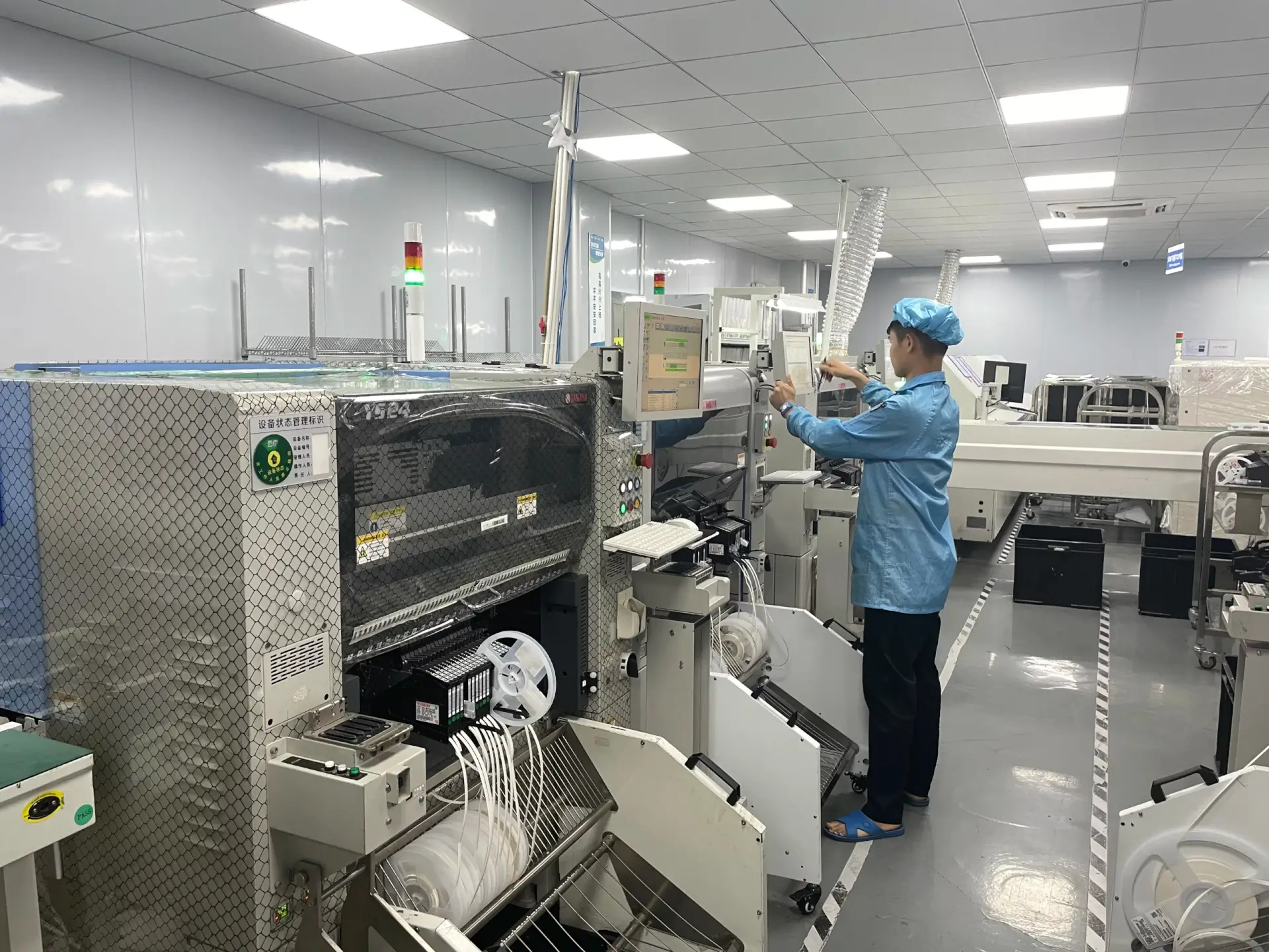
The preheat slope matters as much as the final temperature. A ramp of 1 to 2 °C per second keeps the flux active without boiling the solvent off before the wave is reached, and a steeper ramp usually forces an increase in contact time to compensate, as covered in the wave soldering guide.
Flux Activation and Thermal Demand
Flux has to be active at the moment the board meets the wave. A flux applied at the entrance of the machine and dried out by the time it arrives has already lost most of its activity, and no amount of contact time will restore it. Spray flux and foam flux deliver different amounts, so the preheat that suits one may dry the other out before the wave is reached.
Thermal demand rises with copper. A ground plane connected to a barrel draws heat away from the joint faster than an isolated pad, so boards with heavy copper usually need a higher preheat and a slightly longer contact time than the same design on signal-only layers.
Solder Pot Temperature and Alloy
The solder pot is normally held between 245 °C and 260 °C for a lead-free alloy, and the temperature is set so the wave delivers enough heat without oxidising its surface. Lower pot temperatures require longer contact times, which raises the thermal dose to the laminate.
Copper dissolving into the pot raises the liquidus temperature of the alloy slowly, and the change stays invisible until joint surfaces begin to look dull. Periodic alloy analysis keeps the pot inside its specification, as described in the notes on solder pot alloy analysis.
Measuring and Verifying Contact Time
Contact time is verified with a profiler rather than a stopwatch. A thermocouple attached to a barrel wall and a second one on the board surface are run through the machine, and the time spent above the liquidus is read from the curve. The profiler should be the same instrument used for the original approval, because a different unit with a different response time will read a slightly different curve.
The measurement should be repeated for the thinnest and the thickest board in the mix, because one machine setting produces different results on each. Where the two curves disagree by more than half a second, the mix is usually split across two set-ups.
Effect of Pallet and Masking
A pallet raises the board above the conveyor and can reduce the effective immersion depth where the opening is small. Pallet fingers and the mask that shields the bottom side also change the local flow, so a board that fills correctly without a pallet may not fill with one.
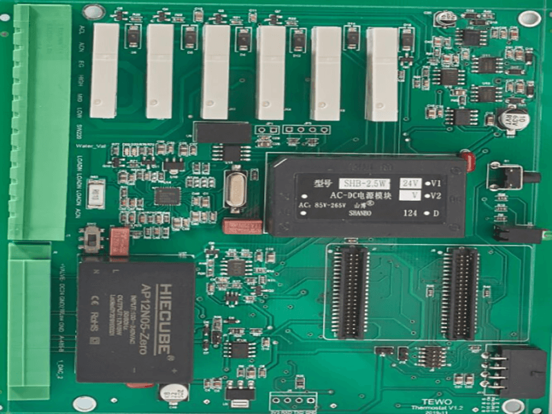
A pallet also acts as a heat sink. Boards on a pallet reach the wave cooler than free-running boards, and the difference is typically 10 to 15 °C at the joint, which appears as a slower fill at the trailing edge of a large connector.
Common Defects and Their Signature
An unfilled barrel with a bright fillet on the top side points to a short contact time or a cold joint at the bottom of the barrel, while a fully filled joint with a rough, grainy surface points to excessive time or an oxidised wave. Defects on the component side, such as shorts under a connector, are easier to miss, so the visual check after the wave should include the shadowed areas beside tall parts.
Bridging between adjacent pins usually comes from too much depth rather than too much time, because a deeper immersion pushes solder over the mask barriers between pads. Icicles and webs form when the board leaves the wave too slowly at the exit, which is a conveyor or wave shape problem treated in the through-hole assembly notes.
Records and Process Limits
The process record should carry conveyor speed, pot temperature, preheat set points, wave height and immersion depth, together with the profile curves for the extreme board thicknesses in the run. gopcb ties those values to the lot number so that a complaint can be traced to the set-up that produced the board.
Limits belong in the instruction as numbers rather than ranges of convenience: a contact time window of 1.8 to 3.0 seconds, a pot temperature window of 245 to 260 °C and a maximum board surface temperature of 120 °C on exit cover most through-hole assembly work.
FAQ
What is a typical wave solder contact time? Between 1.8 and 3.0 seconds for most through-hole assemblies, with the shorter end used where the board is thin and the longer end where heavy copper draws heat away from the joint.
Does a slower conveyor always improve fill? Only up to a point. Beyond roughly three seconds the laminate absorbs enough heat to expand and distort, and the risk of damage to sensitive parts rises faster than the fill improves.
How is immersion depth set? By the conveyor height above the wave crest, normally one third to one half of the board thickness, and it should be re-checked whenever the pallet or the board thickness changes.