Wave Soldering versus Reflow: Process Comparison
Two processes form almost every solder joint in electronics. One deposits paste and heats the whole assembly in an oven, and the other brings the board across a standing wave of molten solder. They produce different joints, have different defect signatures and are often used on the same board, so understanding what each one does well is part of planning an assembly.
How Reflow Soldering Works
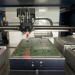
Reflow soldering begins with paste printed through a stencil onto the pads. Components are placed, and the assembly passes through an oven with several temperature zones. The paste is heated, the flux activates and cleans the surfaces, the alloy melts and wets the pads and terminations, and the joints form as the board cools.
The process is a whole board operation, so every joint sees the same profile. That makes it predictable and fast, and it is the reason surface mount technology dominates. It also means that every component must survive the peak temperature, which constrains the parts that can be used on a double sided assembly.
How Wave Soldering Works
Wave soldering applies molten solder to the underside of the board. The board passes over fluxing, preheat and then a pumped wave of solder that contacts the joints and fills the plated holes by capillary action.
The process is selective in the sense that only the underside is contacted, so components on the top side and their joints are not reheated. That makes it suitable for through hole parts, and for assemblies where some components cannot tolerate another reflow cycle.

Which Joints Each Process Makes
Reflow produces a joint between a pad and a component termination, formed by a measured volume of paste. The joint thickness is set by the paste volume and the component stand off, and the fillet is small.
Wave soldering produces a fillet that fills the plated hole and wets the pad on both sides of the board. The result is a mechanically stronger joint with a larger cross section, which is one of the reasons through hole parts remain in use for connectors and power devices. The trade offs between the two technologies for component selection are described in lead-free versus leaded solder.
Flux and Cleaning
Reflow uses flux incorporated in the paste, in a controlled quantity that is printed with the solder. Wave soldering applies liquid flux separately, by spray, foam or wave, and the quantity and uniformity depend on that step.
Flux that remains on the board can be harmless or harmful depending on its type and on the application. No clean fluxes leave a residue that is acceptable for many products but not for high impedance circuits, and water soluble fluxes must be washed thoroughly. Whichever process is used, the residue level should be specified and verified for a product where leakage current matters.
Thermal Profile
A reflow profile has four parts: preheat, soak, reflow and cooling. The preheat brings the board up without thermal shock, the soak activates the flux and equalises the temperature across the assembly, the reflow takes every joint above liquidus, and the cooling solidifies the joint with a controlled grain structure.
A wave profile is controlled by flux application, preheat temperature, wave height, contact time and conveyor speed. The preheat is critical because it drives off the flux solvent and reduces the thermal shock when the board meets the wave. Contact time is short, measured in seconds, so the thermal load on the assembly is far lower than in a reflow oven. Measuring the actual profile with thermocouples attached to the board, rather than trusting the machine settings, is the only way to know what the joints experience; the discussion of a pad design standard assumes a defined profile when it sets the pad sizes.
Defect Signatures
Reflow defects include insufficient paste, bridging between fine pitch pads, tombstoning and voids under area array packages. Most of them originate in the printing step rather than in the oven.
Wave defects are different. Shadowing occurs where a tall component blocks the solder from reaching a joint behind it, bridging occurs between closely spaced leads, and icicles form where the solder does not separate cleanly. Solder skipping on a plated hole leaves an incomplete fill that is often invisible from the top.
Mixed Technology Assemblies
Most boards with through hole parts use a mixed sequence. The surface mount components are printed and reflowed first, then the through hole parts are inserted and soldered, usually by selective soldering rather than by a full wave.
Selective soldering applies the same physics as a wave but in a narrow nozzle, so only the joints that need it are heated. That protects the reflowed joints and the surface mount parts, and it allows a mixed assembly to be built without a second full thermal cycle. For a periodic rework operation, the same equipment can be used to repair a single joint.
Choosing Between Them
Surface mount parts go through reflow, without exception, because there is nothing to wave solder. Through hole parts are candidates for wave or selective soldering, unless the volume is low enough that hand soldering is acceptable.
The quantity of through hole joints also affects the economics. A handful of joints may be cheaper to hand solder than to set up a machine, while a thousand joints justify the process. The decision is therefore about the through hole content and about the thermal sensitivity of the parts already fitted. A board with a few connectors and a heat sensitive sensor may need selective soldering, while a board with hundreds of pins and no sensitive parts can be run over a wave. The second case is increasingly rare, because most products now carry surface mount parts that have already been through an oven.
Process Control
Both processes depend on control of parameters rather than on the equipment alone. Paste volume for reflow, flux quantity and preheat for wave, and the profile in either case, are the variables that produce consistent joints.
The verification method differs. Reflow is monitored by measuring paste deposits and by reading the oven profile; wave is monitored by the flux weight, the preheat temperature and the contact time, with periodic inspection of the joints. In both cases, recording the measurements against the production lot is what allows a defect to be traced to a process excursion rather than to a component, and it is the evidence a customer will ask for when a batch behaves differently from the samples.
FAQ
Can a surface mount part be wave soldered? It can be glued and wave soldered, which is a legacy technique. It is rarely used today because reflow is more accurate and produces fewer defects on small parts.
Which process is more reliable? Neither in general. Reliability follows from the joint design and the process control, and a well made fillet from either process lasts the life of the product.
Does lead free change the choice? It changes the profile and the flux chemistry rather than the choice. Lead free alloys need a higher peak, which makes the thermal sensitivity of the components more of a constraint. The mechanical effects of the joint structure are described in the material on SMT component shift causes.