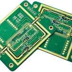
Wire Bonding: Design Rules and Process Limits
Wire bonding attaches a die to a board with fine wires that are welded by heat, pressure and ultrasonic energy. The weld only forms if the surface it is made to is clean, metallurgically correct and flat. A board that is perfectly good for soldering can be unusable for bonding, because the two processes have different requirements and different tolerance for contamination. This article covers what the bonding process needs from the board and how it is verified.
Why Bonding Differs From Soldering
Soldering forms a joint by melting an alloy that wets and reacts with the surface. Bonding forms a weld by deforming the surfaces together under load and ultrasonic vibration until they share a metallic bond. There is no flux to remove oxide at the moment of joining, so the surface has to be correct before the wire arrives.
The absence of flux also means there is no cleaning step to hide a problem. Any contamination on the pad, whether it is oxide, organic residue or a fingerprint, becomes a weak weld. The result is a bond that passes the initial test and fails later under thermal cycling, which is the most expensive kind of failure.
Surface Finish Selection
The finish has to provide a bondable surface on the pads while remaining solderable or otherwise functional on the rest of the board. Gold over nickel is the standard choice for bond pads because the gold does not oxidise and the nickel provides a diffusion barrier. The gold layer has to be thin enough that it does not embrittle the weld and thick enough to be continuous.
Other finishes are used where the board has to be both bonded and soldered, and each has a limitation. A finish that oxidises quickly gives a short window between fabrication and bonding, and one with a rough surface produces variable weld quality. The decision should be made with the bonding process rather than after it, and the general finish trade offs are described in the context of PCB quality assessment.
<img src="https://www.gopcba.com/wp-content/uploads/2026/09/266-4.jpg" alt="Wire bonding capillary forming a gold ball bond on a PCB bond pad” />
Bond Pad Design
The pad has to be large enough for the bond, flat enough for the capillary to seat and separated from its neighbours enough that the wire loop does not touch anything. The bond is made on a defined area, and the pad must extend beyond it so that a slight placement error does not put the bond on the mask edge.
The pad surface has to be smooth. A rough plated surface, an edge from a mask opening that overlaps the pad or a step in the copper changes the energy transfer during bonding and produces a weaker weld. The mask opening should be larger than the pad so that the mask cannot intrude onto the bonding area, and the pad should be free of the via and trace features that create topography.
Plating Quality and Nickel Diffusion
Bonding quality depends on what is underneath the gold. A nickel layer that is too thin allows the underlying copper to diffuse through and oxidise at the surface, which produces a bond that fails after storage. A nickel layer with a high stress or a rough surface transfers that roughness to the gold and produces variable bonds.
The gold thickness is equally important. Gold that is too thick dissolves into the weld and forms a brittle intermetallic, while gold that is too thin leaves exposed nickel. The specified range comes from the bonding process, and the plating supplier has to be able to hold it across the panel rather than only at the coupon. The measurement of the plating layers is part of the incoming verification, and the sampling approach is similar to other assembly measurements.

Contamination Control
Contamination is the most common cause of a bonding problem. It can come from handling, from the plating chemistry, from a cleaning process that leaves residue, from packaging, or from the environment in which the boards are stored. Because the bond is formed without flux, none of these are removed at the moment of joining.
Control requires a chain of custody from plating to bonding. Boards for bonding should be handled with gloves, stored in a controlled atmosphere and interleaved in a way that does not abrade the pads. The interval between the last wet process and the bonding operation should be defined, because a surface that is clean when it is made does not stay clean indefinitely. Where a board must be stored, the storage condition and the maximum interval become part of the specification.
Verification by Pull and Shear Test
Bond quality is verified destructively on a sample. A pull test applies an increasing force to the wire until it breaks, and the force and the failure location are both recorded. A break in the wire indicates a good bond, while a break at the weld or a lift of the pad indicates a process or a surface problem. A shear test on a ball bond measures the weld area in a different way and complements the pull result.
The results should be compared against a distribution rather than a single limit. A batch with a wide spread suggests that something is varying, even if the minimum passes, and the variation is often the earliest indication of a contamination or plating problem. Recording the failure mode with the force turns a test result into diagnostic information, and the joint quality logic used elsewhere, as in solder defect assessment, applies to the interpretation.
Process Window and Thermal Effects
Bonding has a process window defined by the stage temperature, the ultrasonic power, the force and the time. A board with a different thermal mass or a different pad construction shifts that window, so a recipe that works on one product may need adjustment on another. The window should be established with a matrix on the actual board rather than transferred from a similar product.
Thermal history also matters. A board that has already been through a reflow cycle has a different surface than a bare board, and a board with a coating or a residue from an earlier process may not bond at all. The process sequence should be defined so that the bonding operation follows only the steps that are compatible with it, and any change to that sequence should be requalified.
FAQ
Can an immersion gold finish be used for bonding? Yes, if the gold thickness and the underlying nickel meet the bonding requirements. The thickness range is narrower than for a soldering application.
How long can a bonding board be stored? It depends on the finish and the environment. The interval should be defined by the process and verified by bond testing after the maximum storage time.
What causes a bond to fail after thermal cycling? Usually a void or an oxide at the interface that formed during bonding because the surface was contaminated or the plating was not correct.